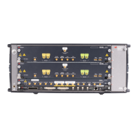
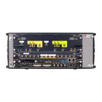
The Trigger Input (TRIGGER IN) has a combined functionality as Trigger or Gate
and is used to start the M8190A by an external signal. This input is defined in
detail in the chapter Sequencing.
The Event Input (EVENT IN) is used to e.g. step through segments or scenarios
by an external signals. This input is defined in detail in the chapter Sequencing.
The Sample Clock Input (SAMPLE CLK IN) can be used, if an external clock
source shall be used to clock the Digital to Analog Converters.
The Sample Clock Output (SAMPLE CLK OUT) can be used to output the clock
signal from the internal sample clock or the sample clock input.
The Reference Clock Input (REF CLK IN) can be used to synchronize to an
external clock. The input frequency can vary between 1 MHz and
200 MHz.
The Reference Clock Output (REF CLK OUT) can be used to synchronize a DUT
to the M8190A. The output frequency is 100 MHz.
The Sync Clock Output (SYNC CLK OUT) can be used to synchronize a DUT to
the M8190A. E.g. the set-up and hold timings of the Trigger Input, Event Input
or Dynamic Control Input signals refer to the Synch Clock Output.
The Dynamic Control Input (DYNAMIC CONTROL IN) offers a 19 bit wide parallel
interface to select the 512 k segments externally. This input is defined in detail
in the chapter Sequencing.
The System Clock Input (SYS CLK IN) and System Clock Output (SYS CLK OUT)
are reserved for future use. Do not connect!
Two LEDs are available at the front panel to indicate the status of the AWG module:
The green ‘Access’ LED indicates that the controlling PC exchanges data with
the AWG module.
The red ‘Fail’ LED has following functionality:
It is ‘ON’ for about 30 seconds after powering the AXIe chassis.
After about 30 seconds the LED is switched ‘OFF’. If an external PC is used to
control the AXIe chassis, this PC can be powered after this LED has switched
OFF.
During normal operation of the module this LED is ‘OFF’. In case of an error
condition such as e.g. a self-test error, the LED is switch ‘ON’.
In case the output relay has shut-off because of an external overload condition,
this LED flashes.
 Loading...
