10
Assemble units as described herein only. To do otherwise
may result in instability. All screws, nuts and bolts must be
tightened securely and must be checked periodically after
assembly. Failure to assemble properly, or to secure parts
may result in assembly failure and personal injury.
Concerto
®
Seating with Power & Data
Assembly Instructions
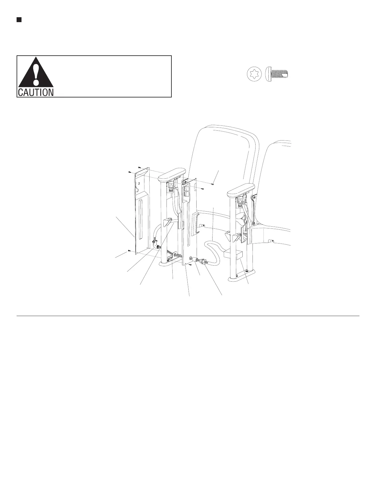
Power Infeed Installation
1. Begin installation by making sure
that a bottom side cover bracket has
been installed and tightened correctly
over the foot of the upright. Orient
the power infeed side cover into
position against the upright and the
bottom side cover bracket. Secure
the power infeed side cover to the
bottom bracket only with two
#8 x
3
/
8
" Torx self-tapping screws.
The top screws may be installed
only if no large tablet arm is to be
attached to the upright. The top two
screws must not secure the power
infeed side cover at this time to allow
for access to install the large tablet
arm (Figure 7).
Note: The power infeeds are to be
connected to the power source by
a qualified electrician who must
also check the electrical integrity
of the finished system (see wiring
schematic, page 17). The steps
below are intended as a guideline for
the installation.
2. Remove the locking nut from the
threaded end of the 90° metal
connector and take off the back
for ease in routing power wires.
Place the threaded end of the metal
connector through the hole in the
bottom side cover bracket and the
attached power infeed side cover.
Thread a
1
/
2
" rigid straight coupler
onto the connector, over the power
infeed side cover. Route the exposed
5-wires, of the power infeed harness,
through the 90° metal connector and
1
/
2
" rigid straight coupler. Pull the
wires tight from the elbow side, to
compress the flexible conduit to its
required length. Replace the back of
the 90° metal connector and secure
the flexible conduit of the power
infeed harness into the 90° metal
connector (Figure 7).
3. Slide the liquid-tight connector onto
the 5-wires and connect it to the
1
/
2
" rigid straight coupler. Slide the
liquid-tight conduit over the 5-wires
and connect it to the liquid-tight
connector. Finally, the liquid-tight
conduit may be cut to appropriate
size, fastened to the junction box
and the 5-wires may be connected to
the power source (junction box not
provided)
(Figure 7).
4. For a power infeed upright
requiring a large tablet arm, refer to
“Large Tablet Arm and Side Cover
Installation” steps 2, 3 and 4
(page 9). For a no-tablet full-height
side cover, skip to step 4 in the same
section.
5. Secure the top of the power infeed
side cover with two #8 x
3
/
8
" Torx
screws at this time (Figure 7).
/”Pan Head Self-Tap T-20 Torx
3
8
7
#8 x /”Torx
-tapping screws
3
8
90° metal
connector
5-wire
power infeed
harness
bottom side
cover bracket
junction box
(not furnished)
liquid-tight
conduit
#8 x /”Torx
self-tapping screws
3
8
tablet arm
full-height
side cover
(right-hand end)
power infeed
side cover
liquid-tight
connector
1
/”rigid
straight
coupler
2
 Loading...


