14
Assemble units as described herein only. To do otherwise
may result in instability. All screws, nuts and bolts must be
tightened securely and must be checked periodically after
assembly. Failure to assemble properly, or to secure parts
may result in assembly failure and personal injury.
Concerto
®
Seating with Power & Data
Assembly Instructions
ADA Removable Base - Standard
Concerto Seating
Note: ADA Removable Bases are
not available with power & data.
The instructions below detail the
installation of the uprights to the
ADA removable base using the
glides, nuts and caps provided. They
will refer to sections of the standard
Concerto Seating Assembly
Instructions for completion. It is
important to follow them during
assembly.
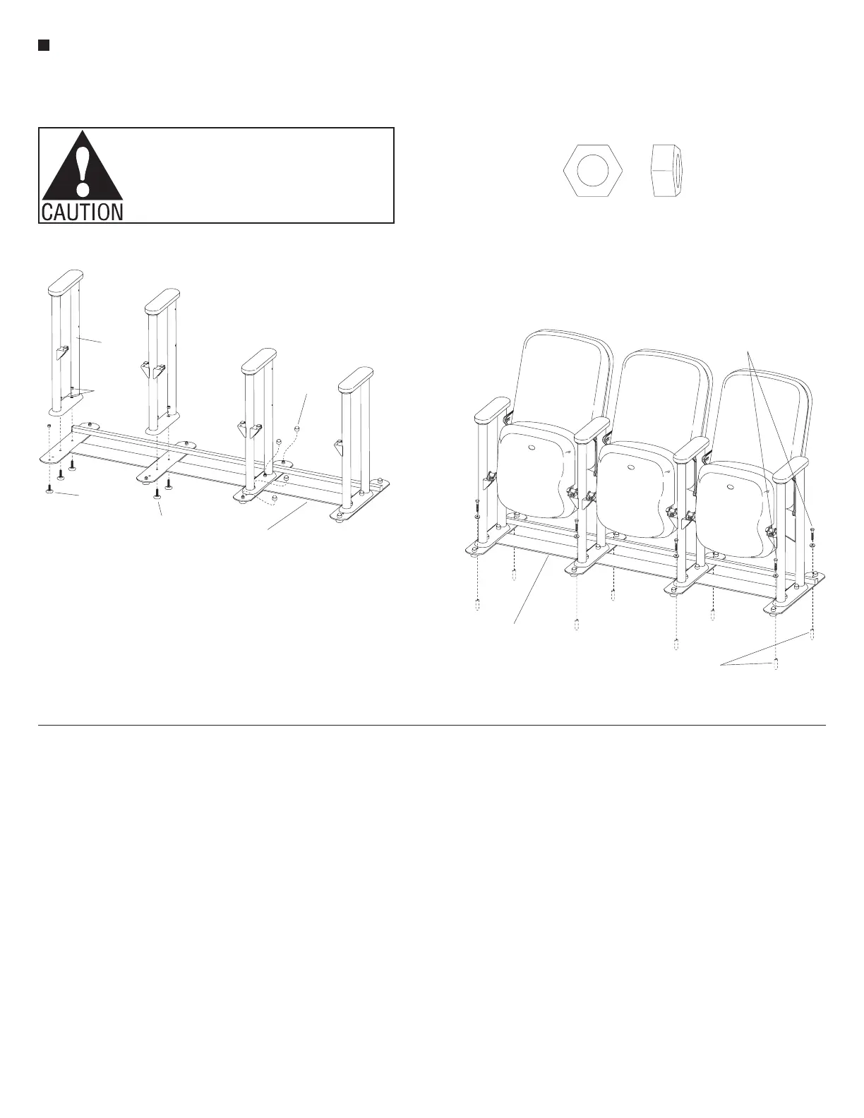
1. Locate the glides that attach
underneath the base strips. Glides
with
5
/
8
" long stems must be installed
at the end of the foot, while the glides
with 1" long stems install in the
middle of the base strips. Insert the
appropriate glides up through the
ADA base and the mounting holes in
the foot of each upright. Secure the
components together with
5
/
16
" hex
nuts on the glides (Figure 12).
2. Place a plastic dome cap on top of
each glide stem, above the installed
5
/
16
" hex nut (Figure 12).
3. Refer to pages 5 and 11 of the
Concerto Auditorium Seating with
Power & Data Assembly Instructions.
Follow instructions for “Back
Attachment” and “Seat Attachment”
as described. If equipped with
accessories like tablet arms or end
panels, refer to page 12 or 13.
4. Place the assembled ADA removable
base/Concerto Seating assembly in
the desired location for mounting
to the floor. Mark the location of the
mounting holes on the floor and
move the unit out of the way for
drilling.
5. Drill mounting holes and install
anchoring hardware in the floor.
Anchoring hardware is not provided.
Follow the appropriate requirements.
6. Reposition the unit and secure to the
floor following the “Floor Fastener
Requirements” (Figure 13).
7. For removal of the unit, remove the
hardware that anchors the ADA base
to the floor and move the unit. To
reinstall, repeat step 5 (Figure 13).
Note: Take great care when
removing and installing the unit.
Damage to the anchoring hardware
may result in expensive repairs to the
floor and anchoring hardware.
Caution: Unit must be properly
fastened to the floor. Failure to
properly fasten unit to the floor may
result in instability of the unit and
personal injury.
ADA
removable base
upright
5
/”hex nut
16
plastic
dome
cap
glide with
/”stem
5
8
glide with
1” stem
grade 5 bolt & flat washer
(not furnished)
grade 5 expansion anchors
(in concrete)
(not furnished)
ADA removable base
to Seating assembly
5
/”hex nut
16
 Loading...


