8
Assemble units as described herein only. To do otherwise
may result in instability. All screws, nuts and bolts must be
tightened securely and must be checked periodically after
assembly. Failure to assemble properly, or to secure parts
may result in assembly failure and personal injury.
Concerto
®
Seating with Power & Data
Assembly Instructions
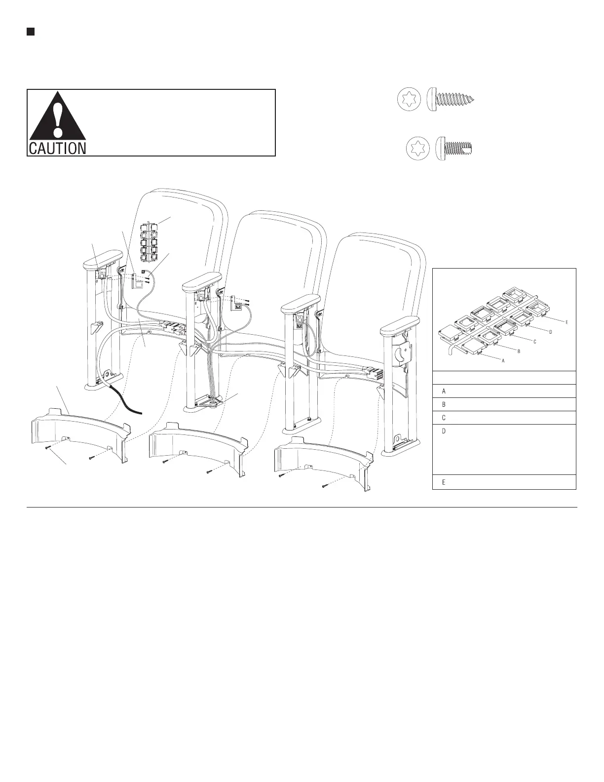
Data Wire Installation
1. At the data infeed location, be sure
that a data bracket has been installed
on top of the foot of the upright and
that the data wires run up through
the opening in the bracket (Figure 5)
(Also reference “Data Infeed” section
view, page 17).
2. At the data infeed location, route the
data wires up between the upright
tubes and direct them right or left,
under each back. Leave enough
slack in the wires to allow
for installation of the lower
wireway covers and side covers
after nal data connections are
made (Figure 5).
3. Install the lower wireway cover by
first directing the two top tabs up
between the backboard and the back
panel of the installed back assembly.
Align the two holes of the lower
wireway cover with the holes in the
back panel and secure with two
#8 x
1
/
2
" Torx screws per cover
(Figure 5).
Note: A variety of data adapters
may be used in the following step.
The data adapters must match the
data plate. Your component design
and installation procedure may vary
(Detail A).
4. Fasten the data bracket to the
simplex receptacle using two
#8 x
3
/
8
" Torx screws. A variety of
data jacks can be accommodated by
picking from the tree of data adapters
(Figure 5 & Detail A).
5. Make the appropriate data wire
connections and snap into the data
adapter.
Large Tablet Arm and Full-Height
Side Cover Installation
Note: It is important that tablet arm
side covers and the large tablet arms
are installed before any other side
covers. Large tablet arm side covers
can be right-hand or left-hand
and full-height or half-height.
For installation of power infeed
side covers see “Power Infeed
Installation.” The instructions and
Figure 6 depict a left-hand end
tablet arm, full-height option. Your
configuration may vary.
1. Carefully maneuver the tablet arm
side cover (left-hand end shown)
against the upright to align the upper
and lower mounting holes with
the holes in the top of the upright
and the bottom side cover bracket.
Secure the cover to the upright with
four #8 x
3
/
8
" Torx screws (Figure 6).
Note: When a tablet arm is installed
to an upright without a tablet arm
side cover, a nylon washer must
be installed between the tablet
mechanism and the pivot mount
bracket per step 2 below.
2. Insert the
3
/
8
-24 x 1.618" hex washer
head Matpoint bolt through the tablet
arm mechanism. If a tablet arm side
cover is not to be installed to the
tablet arm upright, place a nylon
washer onto the
3
/
8
-24 hex washer
head bolt at this time (Figure 6).
Note: Tablets with the wood armcap
option will come from the factory
with a UHMW protective strip added
to the underside of the tablet.
3. To avoid cross-threading and
jamming of mounting bolts, do not
use impact drivers to install
tablet hardware. Rest the tablet
mechanism onto the armcap and
Letter
Phone/Data Jack
Opening Size
None Blank
.635 x .730"
.670 x .929"
.585 x .780"
Panduit "KJ" & "KJA"
Amp CAT-3 & CAT-5
Hubbel "HD5", Ortronics
"OR-6295003-T568B" &
"OR-6295004-T568A"
Krone, Leviton "41108-RE5"
.680 x .710"
AT&T
Ortronics "TrakJack"
Panduit "C"
A
Data Adapters
#8 x
/”Pan Head T-20 Torx Screw
1
#8 x
/”Pan Head Self-Tap T-20 Torx Screw
3
data
adapters
data
plate
simplex
receptacle
#8 x /”
3
8
Torx screw
lower wireway
cover
back
panel
#8 x /”
1
2
Torx screw
data infeed
bracket
 Loading...


