Appendix C: Applications
P/N 3102351-EN • REV 005 • ISS 28DEC18 227
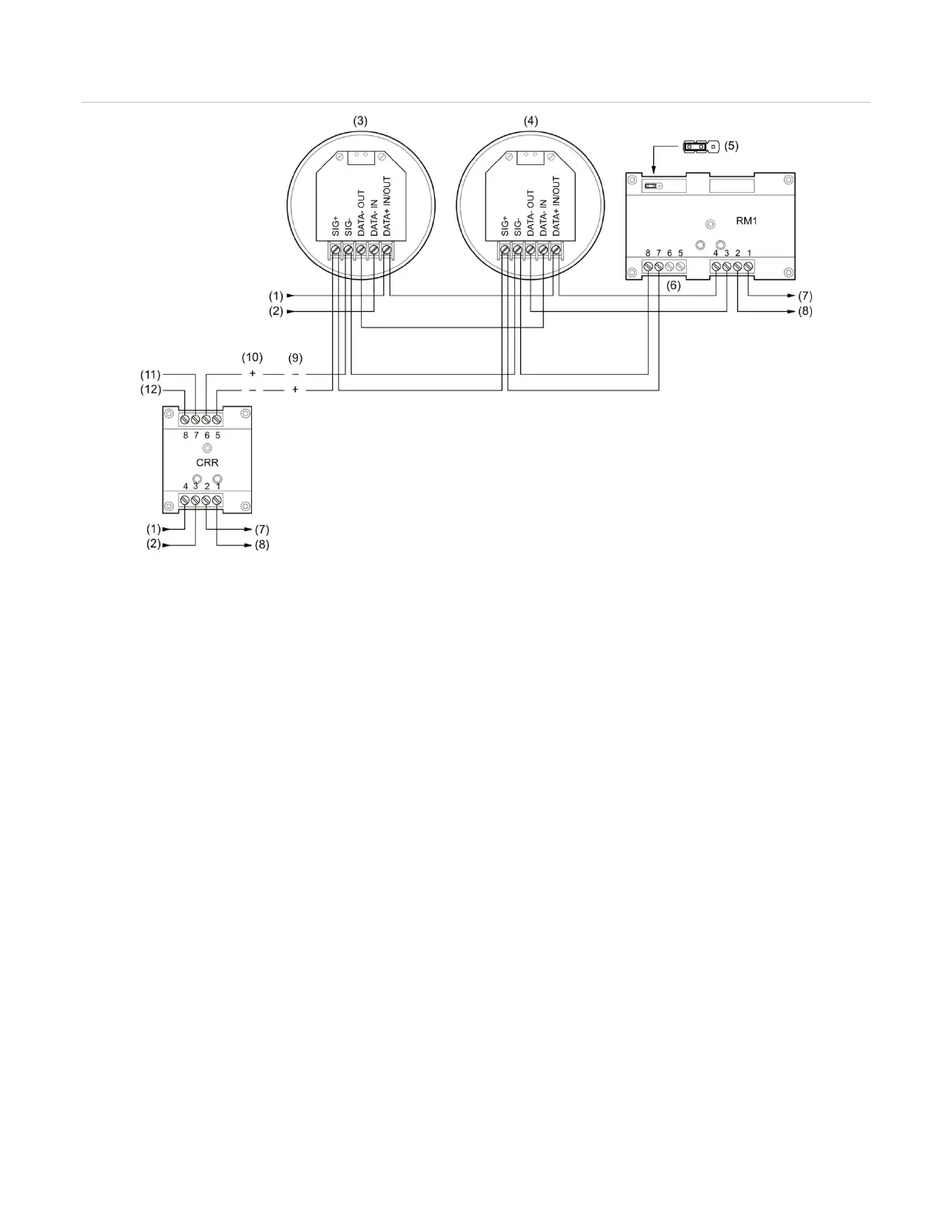
Figure 59: Typical wiring for a zone alarm signaling application
SLC IN −
First detector
Last detector
JP1:L 24 VDC monitor
NC (no connection)
(8) SLC OUT −
(9) Active
(10) Normal
(11) AUX riser 24 VDC +
(12) AUX riser 24 VDC −
Notes
• A polarity reversal module can be used to provide power to the sounder bases. You can omit the polarity
reversal module if correlation groups are used to activate the sounder bases.
• The RM1 module is used to monitor riser polarity. You can also use a CT1 module and a PAM-1 control relay
for this purpose.
Programming for zone alarm signaling
This application requires that you group detectors into zones and correlate inputs and outputs
for each zone. Zone alarm signaling is a type of correlated signaling: You can set up a zone
alarm signaling application by creating correlation groups for specific zones. When using
correlation groups, detectors are added to the input side, and polarity reversal modules are
added to the output side of one or more correlation groups.
The following instructions are written for “Zone 1” but can be applied to any zone.
Note: For PS/PD, PHS/PHD, IPHS, and SD detectors configured as “Supervisory Non-
latching” device type or for PCOS/PCD detectors (smoke element) configured as “Smoke
Supervisory Non-latching” device type, if the base is Relay/Sounder, then the follow type
option cannot be configured as “Head.” The follow type in this case should be set to “Alarm.”