18 742.892 | 11.50
EN
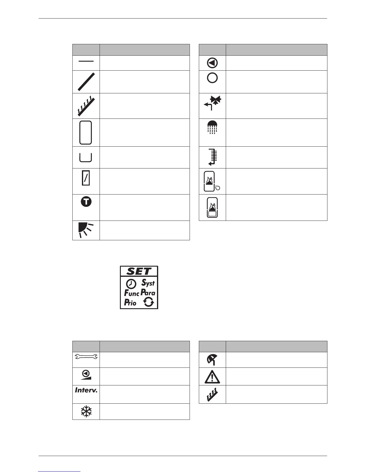
5.2.2 System graphical symbols
The following table describes the symbols used in the system graphics ( in Fig. 8).
Symbol Description Symbol Description
Pipework Pump, switched on
Collector (array) Pump, switched off
Maximum collector tempera-
ture reached
3-way valve with flow direction
Storage tank Domestic water outlet
Swimming pool Cooler for active cooling
External heat exchanger Back-up heating
Temperature sensor Solid fuel boiler
Sufficient solar irradiation
available for loading
5.2.3 Settings menu
The settings menu ( in Fig. 8) contains the following entries:
Time System
Functions Parameters
Priority Reset to factory defaults
5.2.4 Pictograms for functions
The following table describes the pictograms used for functions ( in Fig. 8).
Symbol Description Symbol Description
Manual operation
Holiday - recooling
2)
Pump is speed controlled
1)
Alarm output
1)
Interval
2)
Stagnation reduction
2)
Frost protection
2)
1)
Symbol is visible while the function/parameter is being edited in the settings menu.
2)
Symbol flashes: The function is activated and is actively intervening in the control process.
Symbol does not flash: The function is activated and is not actively intervening in the control
process or the function is currently being edited in the setting menu.