DR600 Service Manual
internal DSP. In the meantime, converts the received digital audio from the internal DSP to analog audio,
then send the audio to audio power amplifier(U31), before finally send to the ACCY external interface,
which is to drive the 1W, 16Ω speaker.
3.3.4 Ethernet Interface
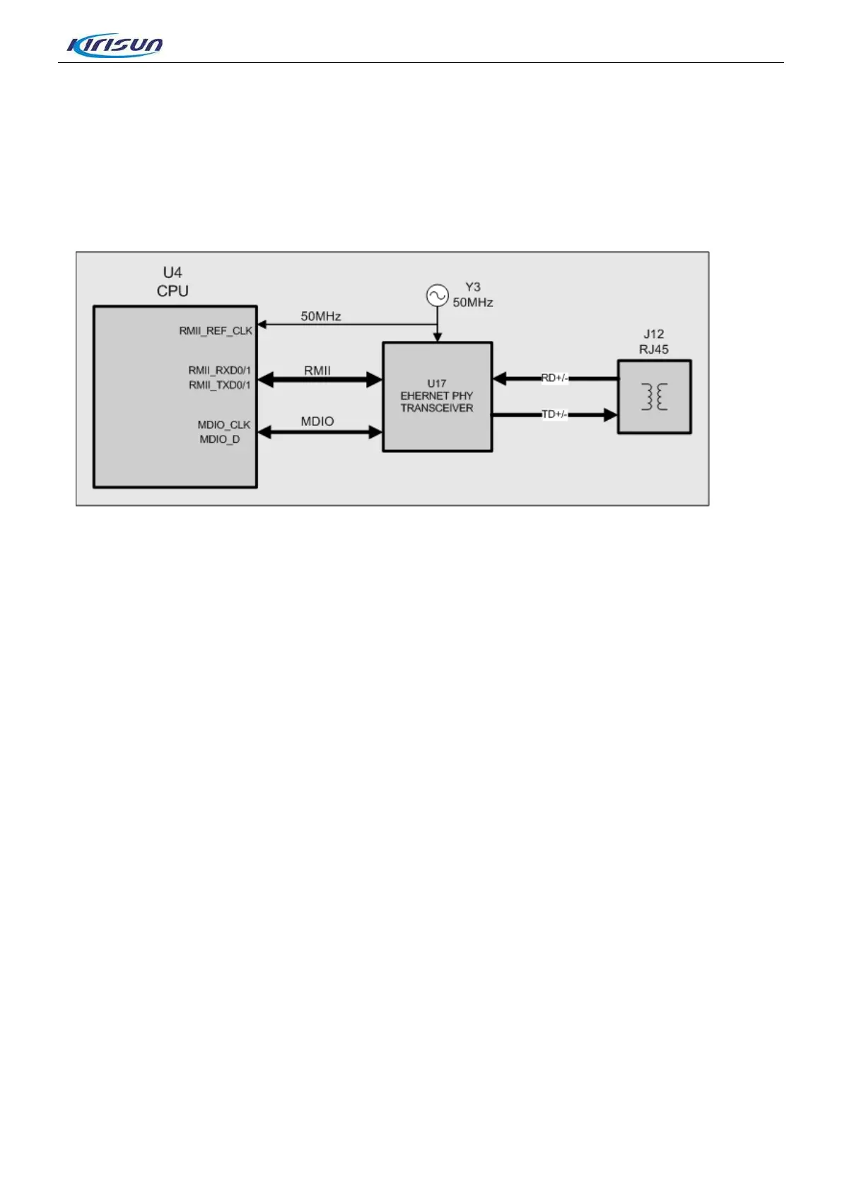
Figure 3-12 Ethernet Interface
As Figure 3-12 shows, A RMII simplified interface is used between the CUP(U4) and network interface
chip(U17) . RMII interface independent clock uses external clock mode and share 50MHz clock with U17.
CPU (U4) achieves the hardware information of internet interface U17 through the independent
configuration interface MDIO. CPU also initiate it and assign MAC and IP address.
The data transmitting and receiving between network interface chip(U17) and interface connector(J12) are
achieved through connecting the transformer inside the connector jack RJ45 and LED through 2 pairs of
differential line.
The network interface can realize parameter adjustment and parameter configure, user programming and
firmware upgrade.
3.3.5 Boot Mode
A boot mode selection switch (J4) is provided on the baseband. The four position 1 to 4 of DIP encode
switcher are correspondingly connected with boot 1 to boot 4 of OMAP (U4), so the boot operation mode
will be changed after being powered on.
The level of position “ON” of encode switcher corresponding to boot which is connected to GND is
“0”.Conversely, the level of position “OFF” is “1”.
As showing in Figure 3-13, the level of boot1 to boot4 of switcher is 0101, and it enters to firmware
download mode after power on. It can upgrade the guide program and the low driver program by booting
from serial port(UART2).
15

 Loading...