DR600 Service Manual
2. Product Controls and LED Indicator
Introduction
2.1 Product Controls
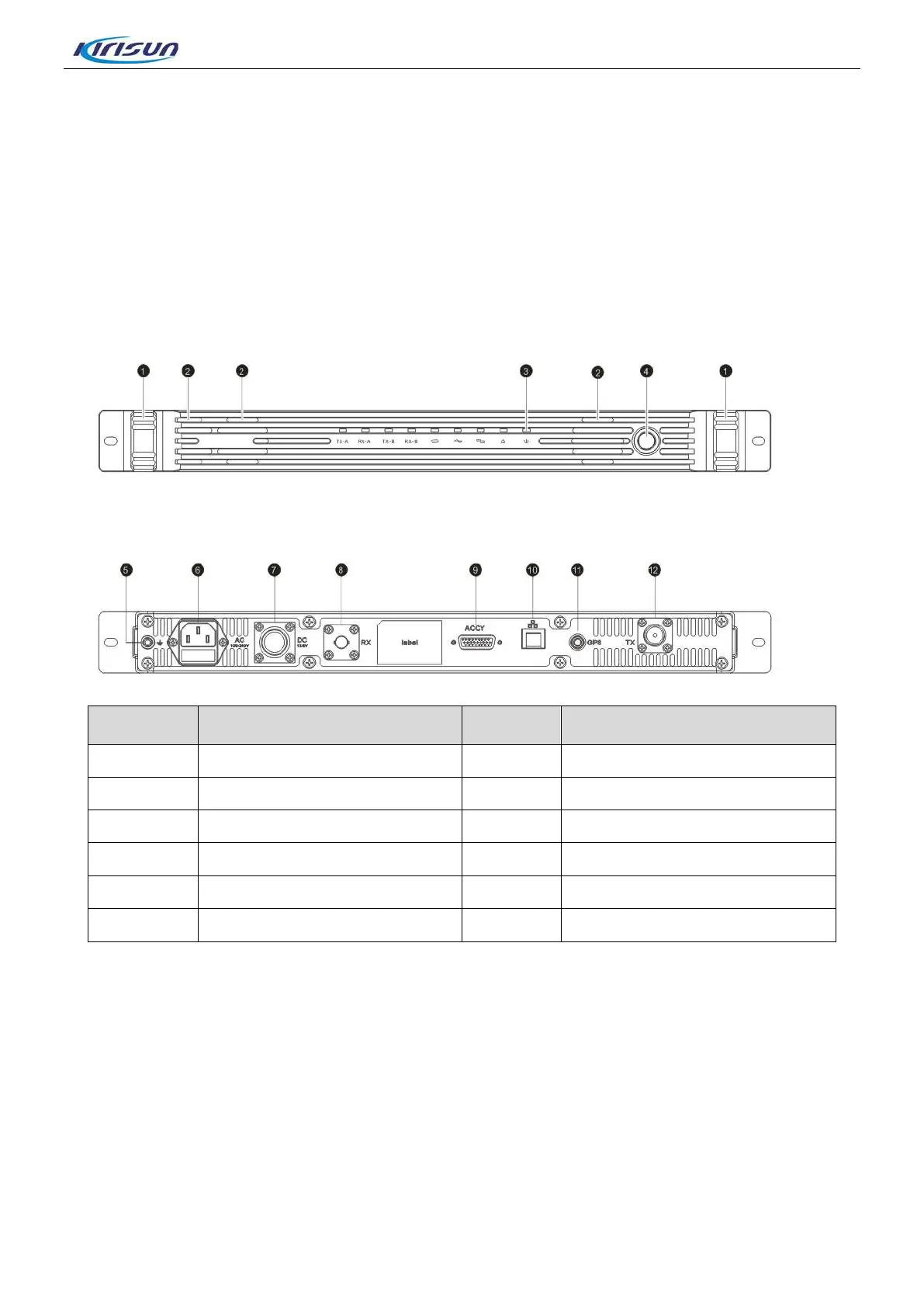
The appearance of the the DR600 repeater is shown in the Figure 2-1.
Figure 2-1 DR600 Appearance
No. Part Name No. Part Name
1 Handle 2 Fan
3 LED Indicator 4 Power Switch
5 Grouding Rod 6 100~240V AC port
7 13.6V DC port 8 RX Interface
9 ACCY interface 10 Ethenet Interface
11 GPS interface 12 TX Interface
2

 Loading...