DR600 Service Manual
3.3.15 Case External Interface Definition
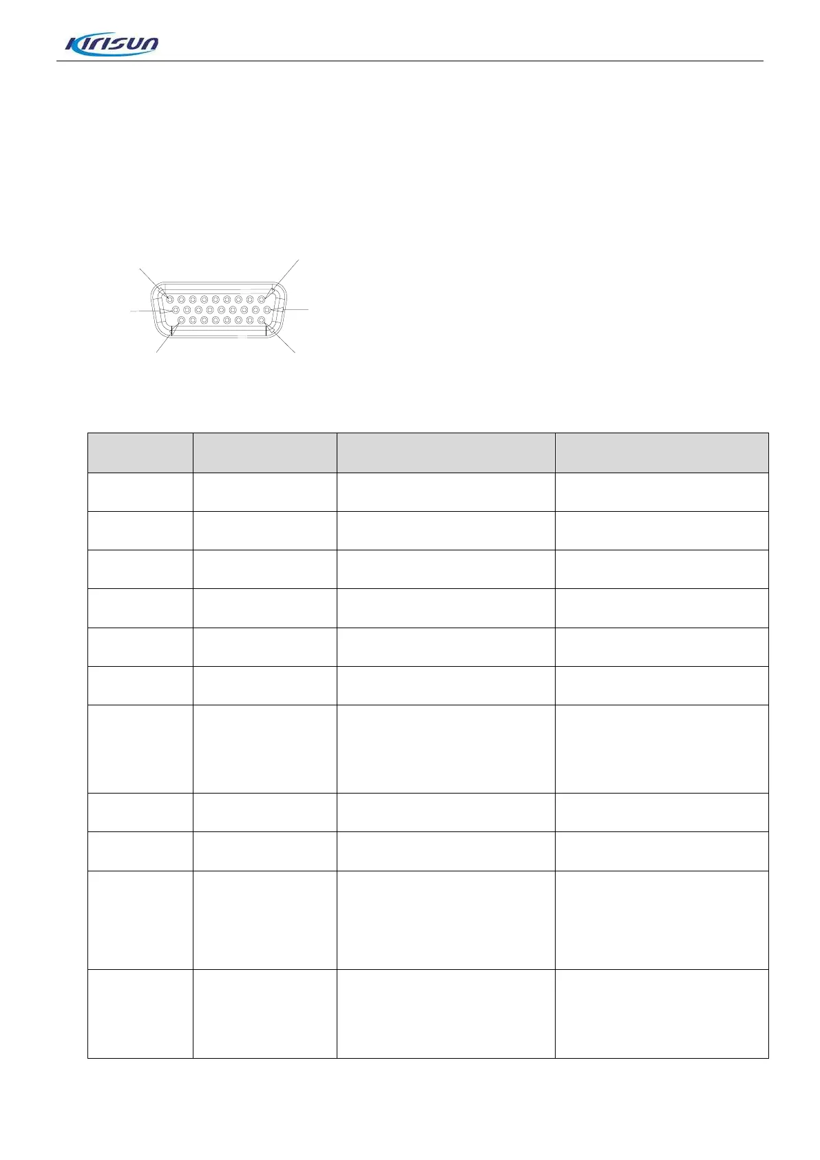
Extended interface (J9) of baseband is connected to accessory board by a flat gray cable, then connected
to the ACCY connector at the rear of repeater after conversion through accessory board. The ACCY
connector is as following Figure 3-24.
Figure 3-24 ACCY Interface
Terminal NO. Terminal Name I/O Function
1 Ext_SWB+ +13V Output +13.8V output(Imax<1A)
2 GND Ground Ground
3 USB_D+ Reserved
4 USB_D- Reserved
5 USB_VBUS Reserved
6 USB_GND USB Ground
7
Program_IN_1
(PTT)
External PTT Signal input, High
level active .when connected
with Pin20, enter transmission
mode
Digital Input:
(2.5V<VIH<3.3V,0V<VIL<0.4V)
8 Ext_Spk- External Speaker output 8 Ω /16Ω, 0.8W Max
9 Ext_Spk+ External Speaker output 8 Ω /16Ω, 0.8W Max
10 ACC_MAP_ID_2
Accessory ID input Line 2
Control signal, when connected
with Pin20, mode of analog RX
performance testing
Digital Input:
(2.5V<VIH<5V,0V<VIL<0.4V)
11 ACC_MAP_ID_1
Accessory ID input Line 1
Control signal, when connected
with Pin20, the IP address will
be set to the default address:
Digital Input:
(2.5V<VIH<5V,0V<VIL<0.4V)
26

 Loading...