DR600 Service Manual
J6、J7 are 12.8MHz clock and SMA offered by main board to other parts. The two signals are the same
and either one of them can be selected.
J8 is the interface and SMA of GPS interface, and it supports active antenna with 3.3V feed output.
J9 is the ACCY external interface provided by baseband, and it is used for function expansion or test.
It includes the input and output of local speech, external PTT, and programmable expansion IO. It provides
12V/1A DC output.
J15 is the interface of Rx board, including digital IF, SPI interface signal, 12C interface signal for storing
data of test and adjustment, etc.
J17 is the interface of Tx board, including two point modulation signal, SPI interface of Tx circuit PLL, Tx
control signal, etc.
J18 is the control interface of RF power amplifier, including SWR , TEMP_DET, POWER_CONTROL,
TX_ENABLE, etc.
J19 is the interface of LED status display board.
J20 is the 12VDC fan interface.The fan will be switched on when the radio transmits or the temperature
goes beyond the set range.
J23 is the serial port UART2.
LED2、LED3、LED4、LED5 indicates program operation status.
LED6 indicates CPU power.
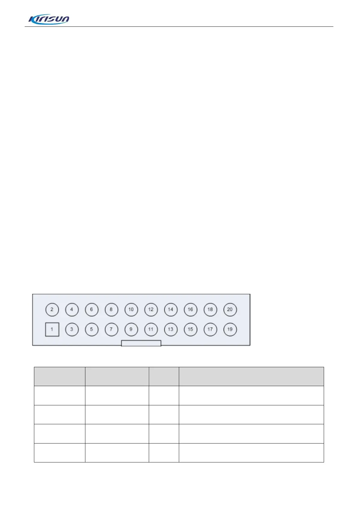
3.3.8 Tx Unit Interface Definition (J17)
Figure 3-17 Tx Unit Interface Definition
Terminal NO. Terminal Name I/O Function
1 GND - Ground
2 MOD1 O TX Modulate signal output1
3 GND - Ground
4 MOD2 O TX Modulate signal output2
18

 Loading...