DR600 Service Manual
The 12.8 MHz reference clock (X100) output signal which is controlled by MODE1 signal will enter the
reference input port of PLL IC (IC100 SKY72310), then according to the configuration of register, it will be
divided to get 3.2MHz reference frequency, and the frequency will be compared in phase difference with the
signal generated by the frequency division which is resulted from the VCO’s enter into the input port of PLL
chip. The PLL (IC100 SKY72310) PD pin will output the positive or negative pulse current which is in output
pulse width, is directly proportional to the aforementioned signal phase difference. When the pulse current
passes the loop filter, it will be converted to CV voltage via RC integral. The the CV voltage will be sent to
the VCO varactor to adjust and control the output frequency from the VCO until the CV voltage becomes
constant. The loop is locked in the meantime.
Buffer Amplifier Circuit
VCO outputs the modulated carrier signal to enter Q2002 for buffer amplication and then passes the LPF
U402 to eliminate the harmonic wave. After that, the signal will go into IC306 for pre-amplification, then
passes the LPF to filter the harmonic wave again, and the signal is output to the SMA connector which is
connected to the transmitting power amplification.
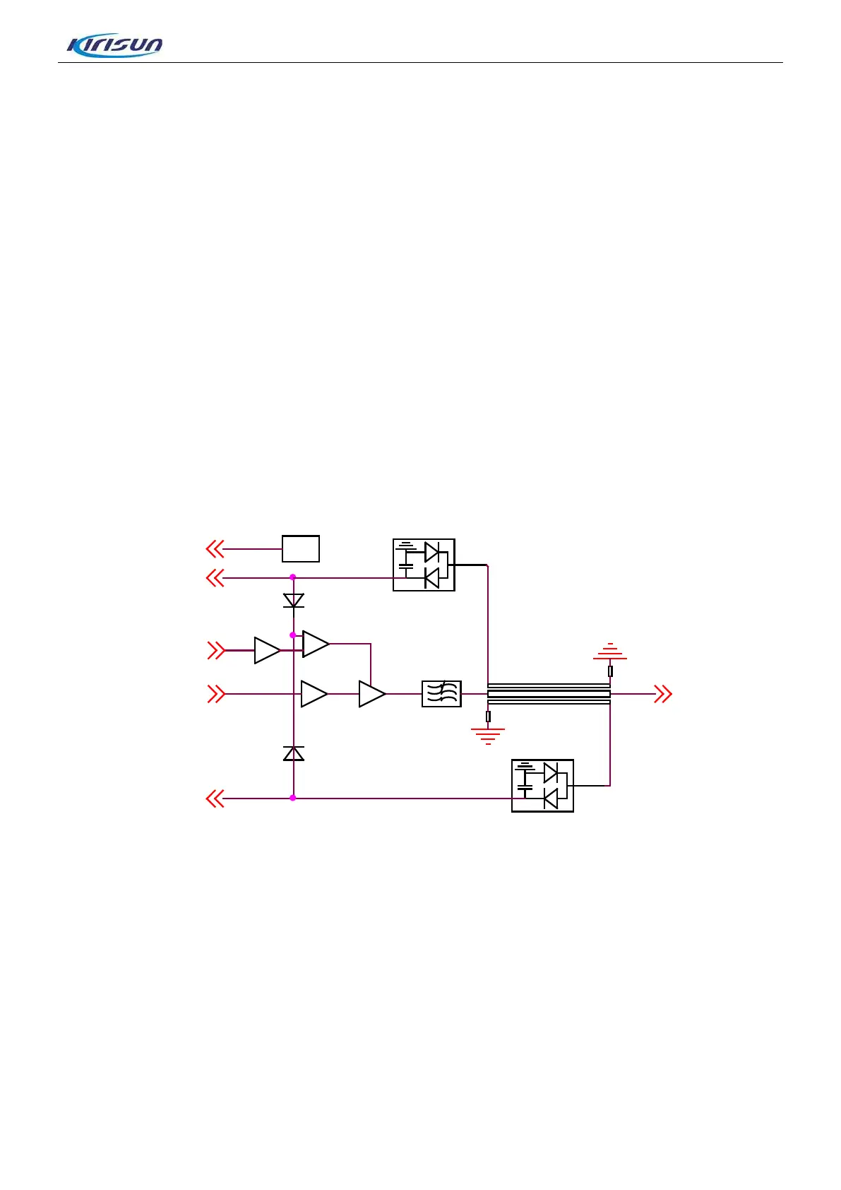
3.1.2 RF Power Amplifier Module Circuit
Figure 3-2 RF power amplification module
D103
SWR-R
IC100
POWERCONTROL
IC101
DS18B20
RFOUT
SWR-T
Q102
RF IN
U100
D104
The power amplifier module will amplify the modulated carrier signal from the transmitter module to a
certain power level, then send to the transmitter port.
The power amplifier module includes the three parts:
Power Amplification Part
The modulated carrier from the transmitter module will enter Q102 for pre-amplification, then the signal will
attenuate to a certain level to make the amplitude of the signal which will be input with U100 operates
between 17~20dBm. Under the control of POWERCONTROL signal, the RF signal output from U100 will
pass the LPF to suppress the harmonic wave and collect power stationary wave sample from the
directional coupler before being sent to the antenna port.
5

 Loading...