TM840 Service Manual
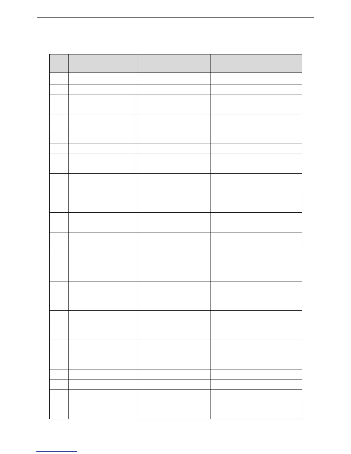
The second development interface includes the functions of audio, programmableI\O, USB, accessory identification, etc.The
pin definition of interfaces as below.
Pin Signal Name Function Signal Definition
1 Ext_SWB+ Power Supply +13.8V output (Imax<1A)
2 Power Ground Ground Ground
3 USB_D+ USB+ USB Data
(2V<V
IH
<3.3V,0V<V
IL
<0.8V)
4 USB_D- USB- USB Data
(2V<VIH<3.3V,0V<VIL<0.8V)
5 USB_VBus USB Power +5V USB Power
6 USB_GND USB Ground Ground
7 Prgm_In_1(PTT) Programmable Input1 (PTT) Digital Input
(2.5V<VIH<5V,0V<VIL<0.4V)
8 Ext-Spk- External SPK- Audio PA Output-
Load impedance: 16Ω typical.
9 Ext-Spk+ External SPK+ Audio PA Output+
Load impedance: 16Ω typical.
10 ACC_MAP_ID_2 Accessory ID Line 2 Digital I/O
(2.5V<VIH<5V,0V<VIL<0.4V)
11 ACC_MAP_ID_1 Accessory ID Line 1 Digital I/O
(2.5V<VIH<5V,0V<VIL<0.4V)
12 Prgm_IO_6 Programmable I/O 6 Programmable I/O
(2.5V<VIH<5V,0V<VIL<0.4V)
(4V<VOH<5V,0V<VOL<0.4V)
13 Prgm_IO_2(Monitor) Programmable I/O 2 (monitor) Programmable I/O
(2.5V<VIH<5V,0V<VIL<0.4V)
(4V<VOH<5V,0V<VOL<0.4V)
14 Prgm_IO_3(Chan_Act) Programmable I/O 3 (Channel
Activation)
Programmable I/O
(2.5V<VIH<5V,0V<VIL<0.4V)
(4V<VOH<5V,0V<VOL<0.4V)
15 Ground Ground Ground
16 Rx_Audio RX audio output Codec Audio Output
(Wmax=15mW@32Ω)
17 Audio_Ground Audio Ground Ground
18 Tx_Audio TX audio Ext_MIC+ Input (VIN<2.0V)
19 Ground Ground Ground
20 Prgm_IO_7 Programmable I/O 7 Programmable I/O
(2.5V<VIH<5V,0V<VIL<0.4V)
9

 Loading...


