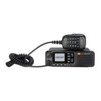
TM840 Service Manual
8 BLC Mic Keypad Backlight Control Digital Output (VOH>2.8V,VOL<0.4V)
9 USB_DP USB+
USB Data
(2V<VIH<3.3V,0V<VIL<0.8V)
10 USB_DM USB-
USB Data
(2V<VIH<3.3V,0V<VIL<0.8V)
Power Supply
Main unit provides two power supply to control panel’s the power. One uses DC3.3V as Tx-Rx LED, backlight light, LCD
module, key scan, and the other power supply (DC13.2V) is for handheld speaker.
Keys
The radio has 12 keys, which are programmable keys(S1.S2.S3.S4.S9.S10), direction keys(S6.S7), menu key(S8),
back key(S5), power button(S12) and emergency key (SW2). Except power button, the other keys are controlled by key
scan chip to finish keys detection identification. The key scan chip passes the identification information to OMAPL138 via
I2C bus, then the processor will implement related operation base on the key scan information.
Status LED and Backlight
The LED enable signal will display basing on the data from the key scan chip. When radio is receiving, the status LED is
green. When the radio is transmitting, the status LED will be red. Press any key, the backlight will be on.
Volume Control
The radio employs waveband encode switch, and the generated volume adjusting signal GPIIO will be sent to OMAPL138
for volume adjusting. The signal is with a 3.3V pull-up voltage,and the phase of two input waveband code will decide the
volume’s change directions, while the quantity of the pulse decides the volume’s varaction.
Chapter 4. PC Programming Mode
4.1 General Functions
(1) Support P-Call, G-Call, A-Call in digital mode.
(2) Support P-Call, G-Call, A-Call in analog mode.
(3) Support Transmit Interrupt function in digital mode.
(4) Support Encryption of both voice and data.
(5) Support Short message, status message and GPS data information.
(6) Support Stun, Unkill, Remote Monitor, Call Alert digital signaling.
(7) Support Self-defined Kill digital signaling.
(8) Support CTCSS/CDCSS in analog mode.
(9) Support MDC1200,2Tone,DTMF,5Tone signaling system in analog mode.
13

 Loading...