TM840 Service Manual
frequency(i.e step frequency f1). The frequency generated by VCO will be harmonics suppress processed twice. Then it
enters the frequency divider of the PLL chip to create frequency f2. F2 will be compared with f1 in phase detector (PD) ,
which will generate a continuous pulse current. When the pulse current passes through the loop filter for RC integration, then
it is converted to CV voltage. The CV voltage will be sent to the varactor of VCO to adjusts and control the output frequency,
till the CV becomes constant. Then the PLL will be locked, the stable frequency output by VCO will go to the TX-RX channel
before passing through two buffet amplifiers.
(2) Working Principle of VCO
VCO employs oscillation mode three point capacitance. It can change the control voltage(i.e CV voltage) of varactor to
obtain different output frequencies. Rx VCO, which provides local oscillator signal, is composed by oscillation circuit and
Q24/Q29, while TX VCO is composed of oscillation circuit and Q27/Q28, and it provides transmitting signal carrier.
Two- Point Modulation
To obtain better modulation accuracy and 4FSK bit error rate when transmitting, two-point modulation is employed. MOD1
and MOD2 send the modulated signal to PLL reference crystal oscillator and VCO modulation end respectively., and to
modulate Tx benchmark crystal oscillator and VCO respectively.
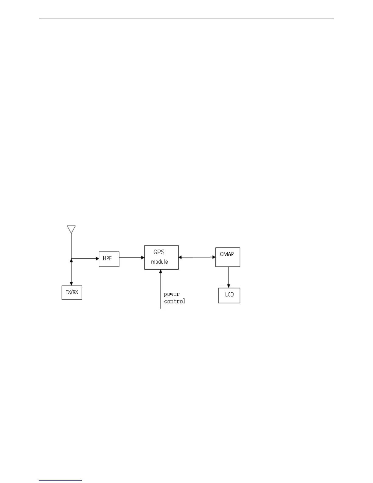
3.1.4 GPS Circuit
Figure 3.6 GPS Circuit Diagram
The radio positioning is achieved by GPS module. This module integrated a baseband processor, a LNA and a SAW. The
GPS signal, whose frequency is 1575.42MHz, is received from the antenna inductor, then passes HPF to filter the Tx/Rx
in-band signal. After a frequency selecting process, the GPS signal will enter GPS module for amplification and filter, then
will be sent to baseband for related calculating. The calculated GPS positioning information will be sent to OMAP for
processing via UART port. In the meantime, U4 can send related command information to GPS module via UART port.
Finally, the processed data information will be delivered to LCD for display by U4.
7

 Loading...


