14
RESISTANCE MEASUREMENTS
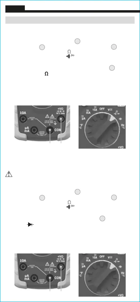
1. Insert RED test lead into VΩ jack
5
, and BLACK test lead
into COM jack
4
,
and rotate function selector switch
2
to the
Continuity/Resistance/Diode
setting.
NOTE: The meter defaults to Continuity testing in this mode. To
enter Resistance testing mode, press the "SEL" button
11
once.
The Resistance icon
will appear on the display.
2. Remove power from circuit.
3. Measure resistance by connecting test leads to circuit. The
meter will auto-range to display the measurement in the most
appropriate range.
NOTE: When in a Resistance setting and the test leads are open
(not connected across a resistor), or when a failed resistor is under
test, the display will indicate O.L. This is normal.
DO NOT attempt to measure resistance on a live circuit.
ENGLISH
OPERATING INSTRUCTIONS
DIODE TEST
1. Insert RED test lead into VΩ jack
5
, and BLACK test lead
into COM jack
4
,
and rotate function selector switch
2
to the
Continuity/Resistance/Diode
setting.
NOTE: The meter defaults to Continuity testing in this mode. To
enter Diode testing mode, press the "SEL" button
11
twice. The
Diode icon
will appear on the display.
2. Touch test leads to diode. A reading of 200-700mV on display
indicates forward bias, "OL" indicates reverse bias. An open
device will show "OL" in both polarities. A shorted device will
show approximately 0mV.
Red leadBlack lead
Red leadBlack lead