13
OPERATING INSTRUCTIONS
CONTINUITY
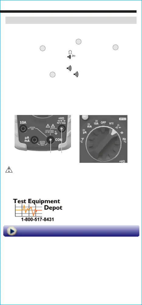
1. Insert RED test lead into VΩ jack
5
, and BLACK test lead
into COM jack
4
,
and rotate function selector switch
2
to the
Continuity/Resistance/Diode
setting.
NOTE: The meter defaults to Continuity testing in this mode. Ensure
that the Continuity Testing icon
is visible on the display. If not,
press the "SEL" button
11
until the icon appears.
2. Remove power from circuit.
3. Test for continuity by connecting conductor or circuit with test
leads. If resistance is measured less than 50Ω, an audible signal
will sound and display will show a resistance value indicating
continuity. If circuit is open, display will show "OL".
DO NOT attempt to measure continuity on a live circuit.
Red leadBlack lead
99 Washington Street
Melrose, MA 02176
Phone 781-665-1400
Toll Free 1-800-517-8431
Visit us at www.TestEquipmentDepot.com