Pressure Independent VAV Applications with CEP/CSP-4000 Series 53 CTE-5202 Applications Guide, AN0912A Rev. D
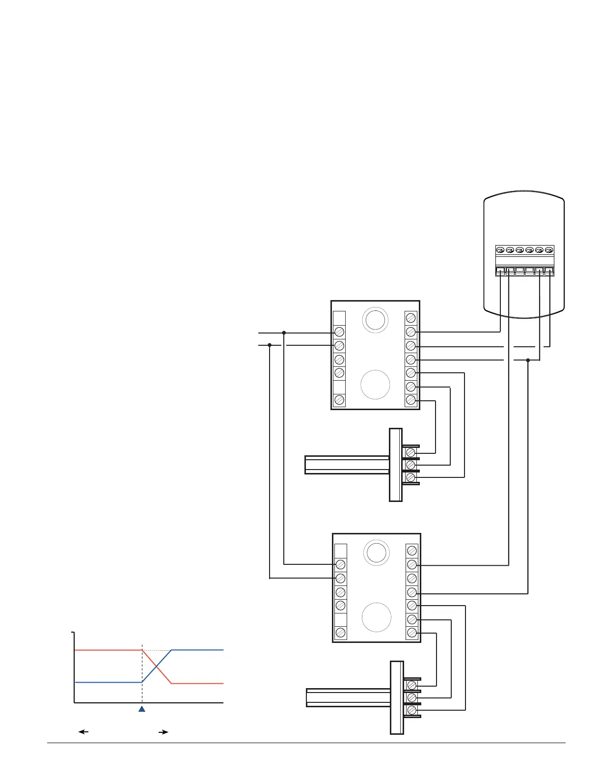
Dual Duct Heat/Cool Constant Volume with Hot Deck Make-Up
NOTE: Minimum and
maximum to be set
on the cooling side
(AO1) in the CTE-
5202 LIMITS menu.
(Heating side makes up
the remainder for the
constant volume.)
Constant volume seing
must be equal to or
greater than cooling
maximum.
Set constant volume
on the heating side by
adjusting maximum
for AO2 to 10 VDC
and adjusting AO2
minimum (volts) for
the desired constant
volume. (See the
Voltage/Velocity
Correlation chart in
the CEP-4000 Series
Applications Guide.)
This application is designed for dual-duct
installations requiring constant air volume (CAV).
In this application, a single-duct cooling controller
is mounted on the cold air duct, and its minimum
and maximum ow is reset by the room thermostat.
A second “slave” controller is mounted on the hot
air duct as a constant volume unit, with the ow
sensor measuring downstream “total ow” into the
space. (The “slave” controller has no reset from the
thermostat.)
As the cold deck resets from maximum to minimum
ow, the hot deck controller senses a decrease in
“total ow” to the space, opens the hot air duct
to compensate, and thus maintains a constant
combined airow into the room.
~
T
T
AI1
AO1
AO2
CTE-5202
Thermostat
24 VAC @ 20 VA
~
–
(Phase)
(Neutral)
1
2
3
7
6
5
4
3
2
1
8
9
10
11
12
13
14
CEP-4xxx
Controller-Actuator
(Hot Deck) SSE-1001/1002
Flow Sensor (Located
in Common Discharge)
1
2
3
7
6
5
4
3
2
1
8
9
10
11
12
13
14
CEP-4xxx
Controller-Actuator
(Cold Deck) SSE-1001/1002
Flow Sensor (Located
in Cold Air Inlet)
Sequence 3 should be selected from the CTE-5202
SYSTEM menu. See Change Conguration on page 6.
(See also the Dual Heating/Cooling Constant Volume
w/ Hot Deck Make-Up section with a CTE-1103 in
the CEP-4000 Series Applications Guide.)
Select Sequence 3
 Loading...