Barber Colman TP-81xx Thermostats Replacement Applications 55 CTE-5202 Applications Guide, AN0912A Rev. D
TP-8101/8102/8103 Replacement (General)
Select Sequence 1
CTE-5202 thermostats can replace TP-8101/8102/8103
thermostats and use the 20 VDC supplied by a
controlled device. (For more information, see the
manufacturer’s installation guide for the controlled
devices.)
CAUTION
Never connect together the red leads (or +20
VDC terminals) of controlled devices with
internal power supplies (with the exception of
MP-52xx actuators—see TP-8101/8102/8103
Replacement with MP-52xx Actuators on page
56).
Heating Air
Heating Max.
Heating Min.
1650
fpm
0 fpm
Setpoint
(Colder Room Temperature Warmer)
3300
fpm
Cooling Max.
Cooling Min.
1650
fpm
0 fpm
Setpoint
(Colder Room Temperature Warmer)
3300
fpm
AO1
Signal
Cooling Air
AO1
Signal
Select Sequence 1 Select Sequence 1
AND set Changeover to 55° F
For cooling, select Sequence 1 (from the CTE-5202
SYSTEM menu). See Change Conguration on
page 6.
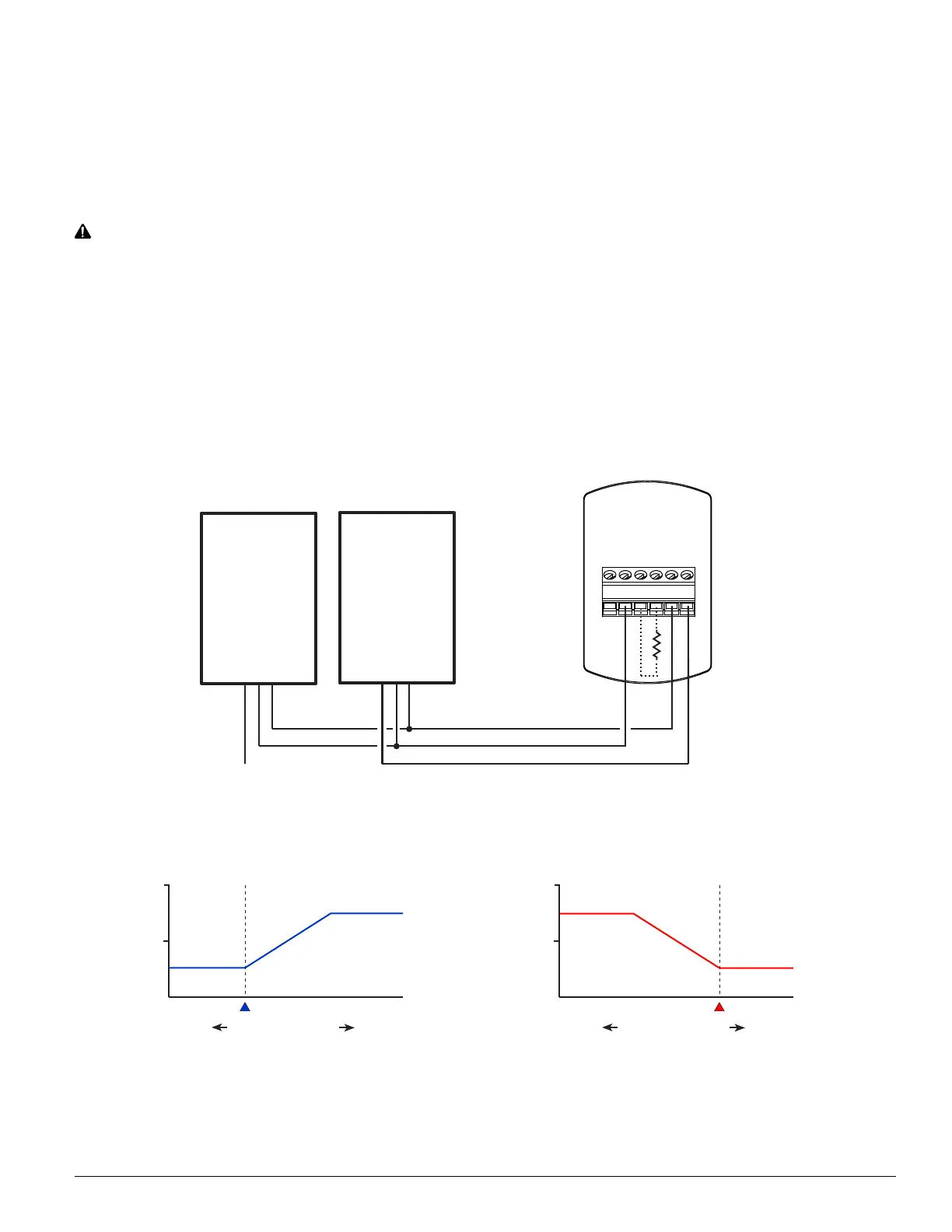
For heating, connect a 5K to 10K ohm resistor
between Common and AI1. Select Sequence 1 and
lower the Changeover to the lowest seing (55° F).
See Change Conguration on page 6. The resistor
simulates a changeover sensor and puts the thermo-
stat in Reverse Acting mode.
NOTE: If the resistor value is too high, the
thermostat will not go into RA mode. If
the resistor value is too low, the thermostat
may go into setback mode.
~
T
T
AI1
AO1
AO2
CTE-5202
Thermostat
Red (+20 VDC)
(5K–10K Ohm
Resistor
between AI1
and Common)
Controlled Device
with
Power Supply
Yellow (IV1)
Blue (Common)
Red (+20 VDC)
Controlled Device
with
Power Supply
Yellow (IV–)
Blue (Common)
(Tape Red Lead
if Present)
 Loading...