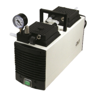
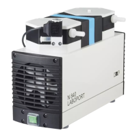
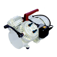
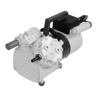
Diaphragm pump N838_E
Servicing
Translation of Original Operating and Installation Instruction, KNF 347394-347605
09/23
39
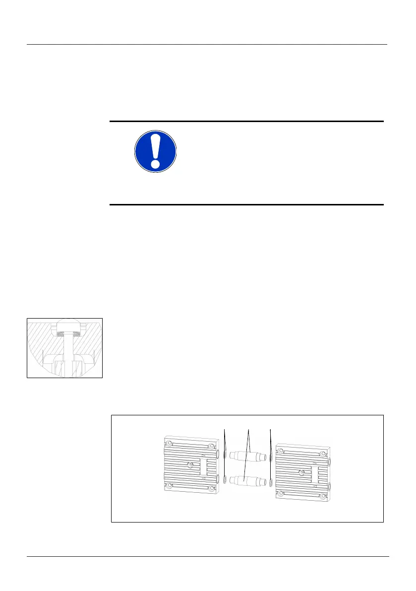
3. Remove the valve plates/seals (6) from the intermediate
plate (2).
4. Check the valve seats, intermediate plate and head plate
for cleanliness; Replace these parts if there are bumps
and scratches on them.
NOTICE
The valve plates/seals are identical for
the pressure and suction side. The
same applies for the top and bottom of
the valve plates/seals.
5. Insert the new valve plates/seals (6) in the valve seats of
the intermediate plate (2).
6. By slightly moving the valve plates/seals horizontally, en-
sure that they are not under tension.
7. Place the head plate (3) on the intermediate plate (2) ac-
cording to the marking (M).
8. With a slight lateral movement of the head plate, check its
centering.
Fig.8: Alignment of
the disk springs
(11)
9. Connect the head plate (3) and the intermediate plate (2)
to each other; to do this, screw in the screws (9) with disk
spring (11) and shim (12). Torque for tightening the
screws: 35 Ncm.
10. Mount the screw covers (10).
11. Perform steps 1 to 9 for the second pump head.
For two-headed pumps:
Fig.9: Removal of connection tubes and O-rings (two-headed
pumps)
EN
-
US
EN