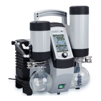
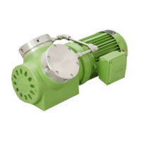
Installation and connection Vacuum Pump System SC 920G
18 Translation of original Operating Instructions, English, KNF 121308-121311 07/18
6.2. Connection
1. Connect the vacuum chamber to the gas inlet's hose connec-
tor (Fig. 2/7, page 11, for hose inside diameter of 10 mm). For
this, vacuum tubing must be used.
2. Connect hose to high-performance condenser in order to
discharge gas exhaust (Fig. 2/17, page 11).
CAUTION
Danger of high performance condenser bursting.
The high
-performance condenser is not pressure-
Do not reduce or regulate the quantity of gas at
the gas outlet, and do not install any compo-
nents that hinder the gas flow.
Safely discharge gas exhaust so that no gas can escape into
the ambient air.
Make sure that the high-performance condenser’s gas outlet is
not blocked (high
-performance condenser is not pressure-
3. Attach coolant feed and return to high-performance condenser
(Fig. 2/19 and 20, page 11).
Connect only the KNF coolant valve (see Chapter 11.2,
Acce
ssories) to the coolant valve connection (Fig. 3/2, page
). Consult with KNF before using any other valves.
4. If necessary: Connect inert gas supply to ventilation connec-
tion (Fig. 2/6, page 11). Observe the safety instructions in
chapter 3.
5. Insert the power cable plug into a properly installed shockproof
socket.