ACT-N02E-1
16
11. ADJUSTMENT
11-1 Potentiometer and limit switches
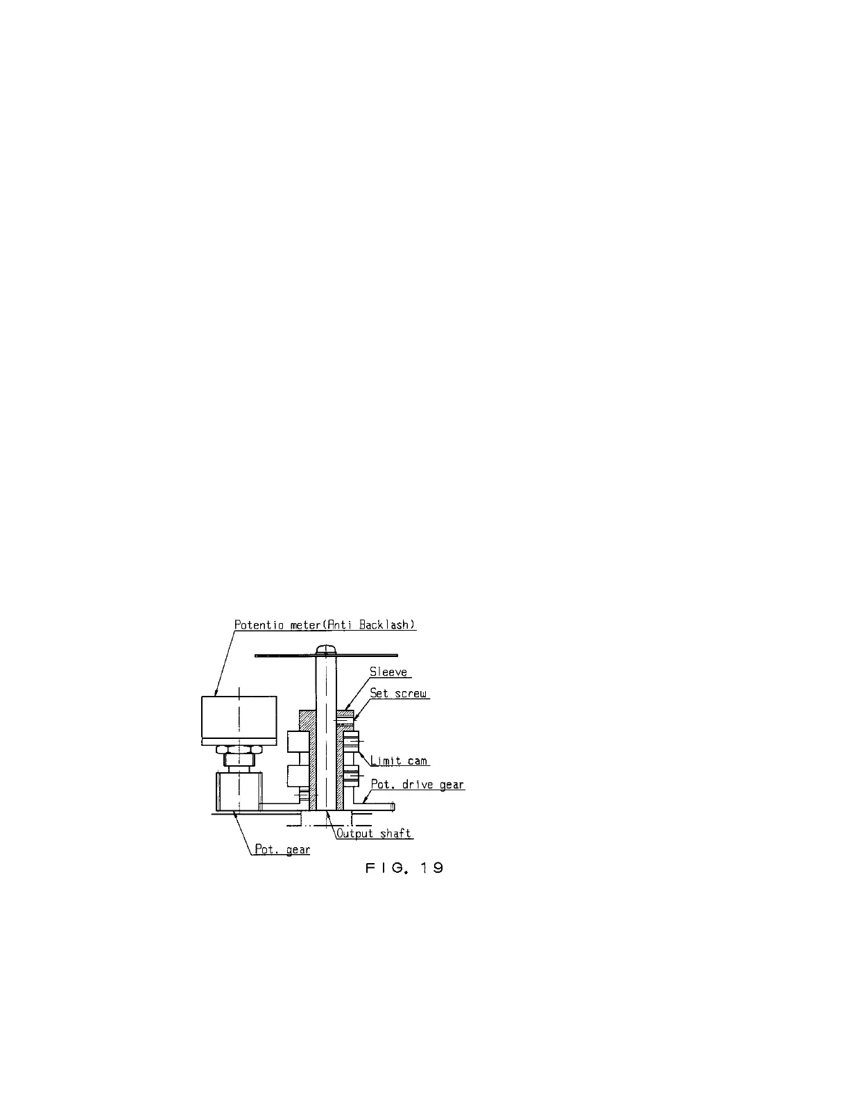
1. Position the Valve position indicator at 50 % manually, and the shaft will come to the position as shown in
FIG.19. (See that the shaft is parallel with the actuator bottom)
2. Connect the adjuster. (FIG.20) :
3. CN1 with control pack, CN2 with actuator
4. Shift the adjuster switch to “ADJ ”.
5. Supply power and signals to control pack.
6. Unscrew and loosen the sleeve.
7. Set the input signal at 12mA, then turn and fix the sleeve at the position where both the adjuster 2 lamps go off.
8. Shift the adjuster to “ACTION ”. If the input signal position is not matching with the potentiometer (as either
adjuster lamp is on), the shaft will self-turn to revise the gap.
9. If the gap is very slight, revise it with ZERO VR at the control pack.
10. Fix the valve position indicator at 50 % position.
11. Set the input signals at 4mA and 20mA, and confirm that the respective shaft positions are matching to the
Valve position indicator.
12. Now the potentiometer adjustment is over.
Adjust the limit switches (OP/CL) as follows :
Loosen the limit cams and adjust the limit switches (Upper = CL, Lower = OP), so as to function at a half
turn of manual handle past 4mA and 20mA points, respectively.
*Ascertain that the mechanical stops will function only at a half turn of manual handle past the limit switches
functional points.
 Loading...