TP-6161 1/12 15Section 1 Specifications and Features
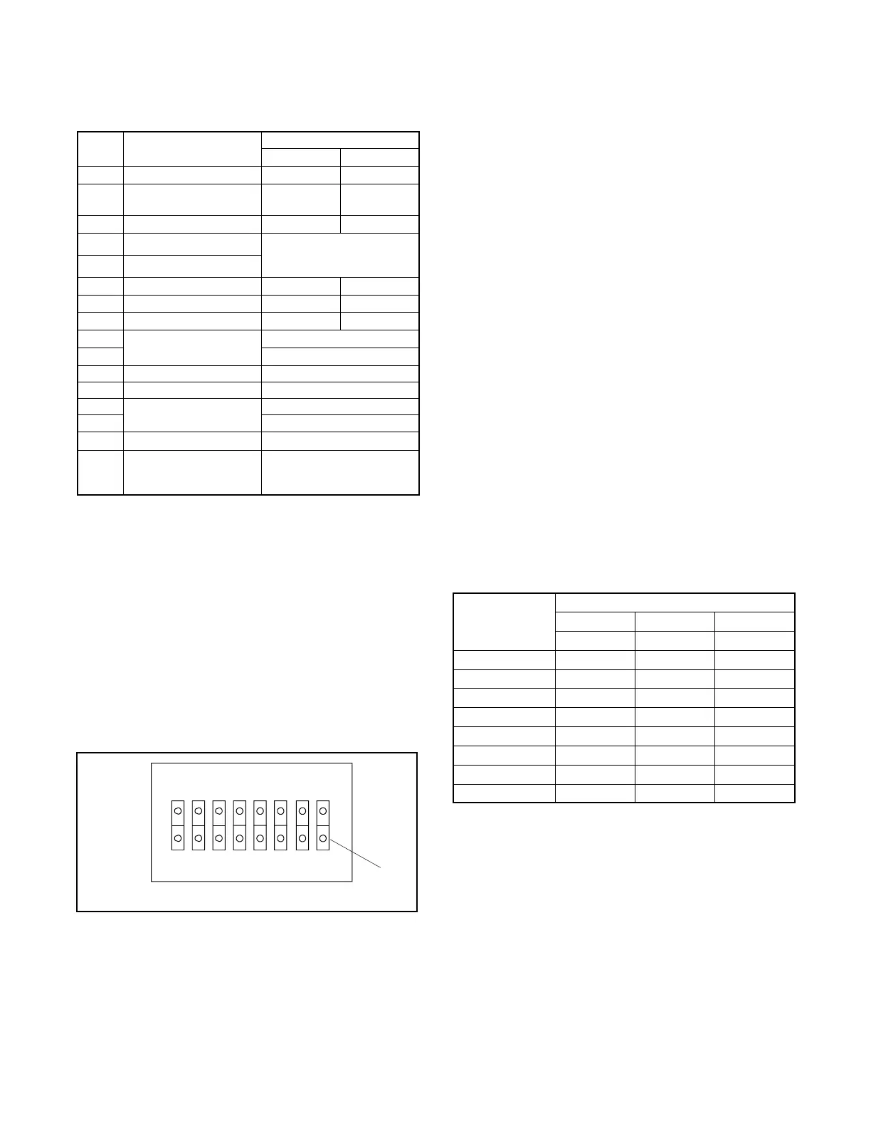
1.2.7 DIP Switches
The controller circuit board contains eight DIP switches,
seeFigure1-9.
DIP
Switch
Descri
tion
Switch Position
Open Closed
1 Overspeed selection 60 Hz 70 Hz
2 Temperature Cooldown
Enable
Cooldown
Disabled
Cooldown
Functional
3 Crank Mode Selection Cyclic Continuous
4 Engine Comm. Setting
See selections for
DIP switch 4 and
DIP switch 5 below
5 Engine Comm. Setting
6
Modbusr Address Bit 0
Value=0 Value=2
7
Modbusr Address Bit 1
Value=0 Value=4
8
Modbusr Address Bit 2
Value=0 Value=8
4
No ECM
Open
5 Open
4 MDEC/ADEC Comm. Closed
5 Isochronous Open
4
J1939 Communication
Open
5 Closed
4 MDEC/ADEC Comm. Closed
5 Governor (VSG)
(Doosan, GM, and
Volvo engine only)
Closed
Figure 1-9 DIP S witch Functions
Note: After setting DIP switches to the generator set
application, be sure to power down and then
power up the controller (disconnect the battery
and then reconnect the battery of the generator
set) or use the prime power switch, if equipped.
The controller will NOT acknowledge the DIP
switch change until after generator set controller
is powered up.
Push down the end of the DIP switch near the OPEN
label to open the switch, or push down the other end to
close it. See Figure 1-10.
6126
1. Push this side down to open circuit.
OPEN
123
1
45 6 78
Figure 1-10 DIP Switch Open Position
Typically, the factory default settings have all the DIP
switches in the closed position except the crank mode
selection switch SW3 which is open for cyclic cranking.
The overspeed selection switch SW1 is open on 50 Hz.
units. Be sure to select the correct DIP switch
configuration for each generator set application.
Overspeed Frequency (DIP Switch 1). The generator
set overspeed frequency is set using DIP switch 1.
Select 70 Hz for 60 Hz voltages and 60 Hz for 50 Hz
voltages.
Temperature Cooldown (DIP Switch 2). The
generator set will continue to run during a five-minute
cooldown cycle or s hut down immediately. The choice is
made using DIP switch 2.
Engine Cranking (DIP Switch 3). The controller is
factory-set for cyclic cranking. To change to the
continuous cranking mode, use DIP switch 3.
Engine Configuration (DIP Switches 4 and 5). See
Figure 1-9 for the DIP switch positions based on engine
configurations regarding non-ECM, MDEC, and J1939
engine communication selections.
Modbusr Address (DIP Switches 6--8). Each
Modbusr device requires a unique address. Address
numbers are created using a binary number system with
DIP switches 6 --8. Figure 1-11 s hows the DIP switch
position for each address number.
Modbusr
Address
DIP Switches
6 7 8
Value=2 Value=4 Value=8
1 Open Open Open
3 Closed Open Open
5 Open Closed Open
7 Closed Closed Open
9 Open Open Closed
11 Closed Open Closed
13 Open Closed Closed
15 Closed Closed Closed
Figure 1-11 Modbusr Device Address
Modbusr is a registered trademark of Schneider Electric.
 Loading...