TP-6161 1/1216 Section 1 Specifications and Features
1.3 Expanded Decision-Makerr 1 Controller
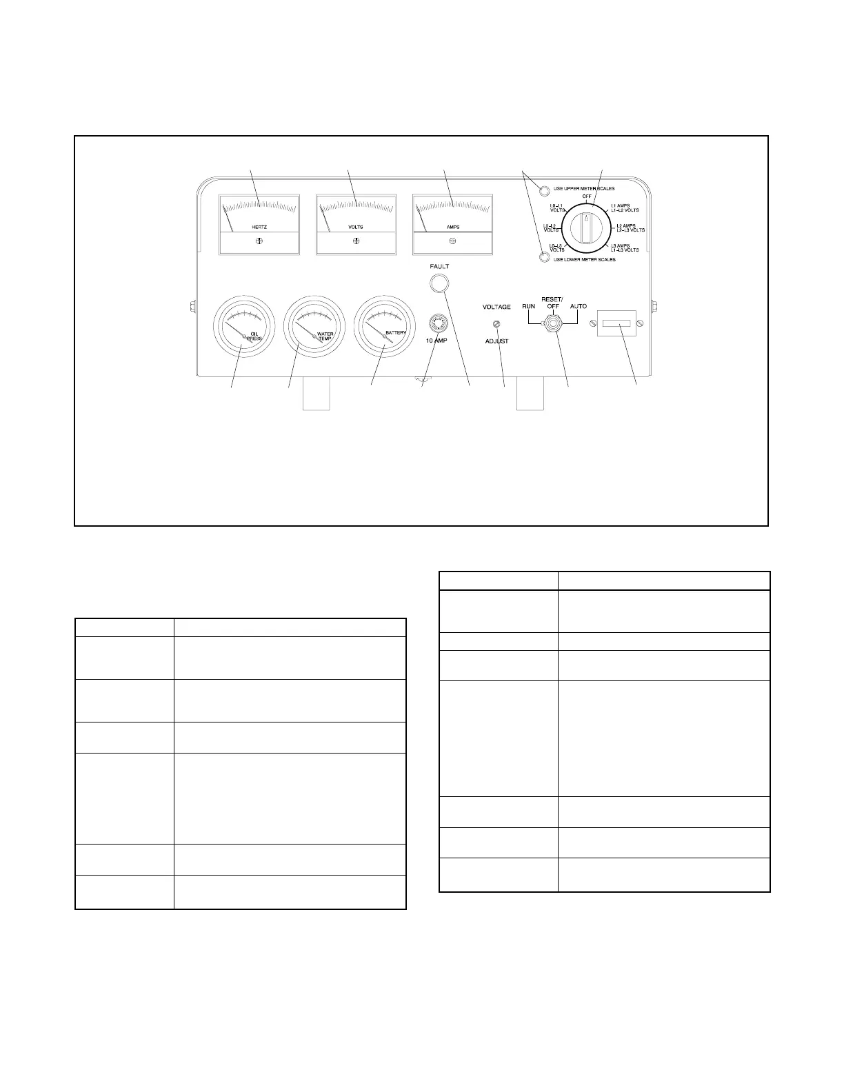
For identification of the expanded controller’s indicators
and controls and their functions, refer to Figure 1-12.
1
10111213
ADV-5849E-B
789
2
3
4
5
6
1. Frequency meter
2. AC voltmeter
3. AC ammeter
4. Scale lamps (upper/lower)
5. Selector switch
6. Hourmeter
7. Generator set master switch
8. Voltage adjustment control
9. Fault lamp
10. 10-amp controller fuse
11. DC voltmeter
12. Water temperature gauge
13. Oil pressure gauge
Figure 1-12 Expanded Decision-Makerr1 Controller
Figure 1-13 and Figure 1-14 describe the controls and
indicators located on the controller.
Item Description
AC ammeter Meter displays the AC output amperage.
Use the selector switch to choose the phase
currents.
AC voltmeter Meter displays the AC output voltage. Use
the selector switch to choose the output lead
circuits.
DC voltmeter Meter displays the voltage of the starting
battery(ies).
Fault lamp Lamp illuminates during engine shutdown if
the engine shuts down because of one of the
following faults: high engine temperature, low
water level, low oil pressure, overcrank, or
overspeed. See Section 2.4.3, Fault
Shutdowns, for additional shutdown
information.
Frequency meter Meter displays the frequency (Hz) of the
generator set output.
Generator set
master switch
Switch functions as the controller reset and
generator set operation switch.
Figure 1-13 Controls and Indicators
Item Description
Hourmeter Hourmeter records the generator set total
operating hours for reference in
maintenance scheduling.
Oil pressure gauge Gauge displays the engine oil pressure.
Scale lamps
(upper/lower)
Lamps indicate which AC voltmeter
and/or ammeter scales to read.
Selector switch Switch selects the generator set output
circuits to measure. When switched to a
position with three circuit labels, the
meters display the amperage on the lead
shown in the upper label and the voltage
between the two leads shown in the
lower label. The AC ammeter and
voltmeter function only with the switch in
the ON position.
Voltage adjustment
control
Control fine tunes (±5%) the generator
set output voltage.
Water temperature
gauge
Gauge displays the engine coolant
temperature.
10-amp controller
fuse
Fuse protects the controller circuitry from
short circuits and overloads.
Figure 1-14 Controls and Indicators, continued
 Loading...