8.9
8
Section 8
Electrical System and Components
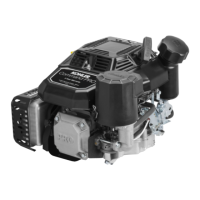
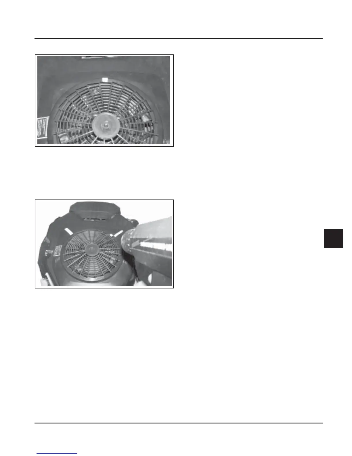
Figure 8-8.
1. Make a line near the edge of the flywheel screen
with a marking pen or narrow tape.
2. Connect an automotive timing light to cylinder
that had good spark.
Test 4. Test the ignition modules and connections.
1. Remove the blower housing from the engine.
Inspect the wiring for any damage, cuts, bad
crimps, loose terminals or broken wires.
2. Disconnect the leads from the ignition module(s)
and clean all of the terminals (male and female)
with aerosol electrical contact cleaner to remove
any old dielectric compound, dark residue, dirt,
or contamination. Disconnect the spark plug
leads from the spark plugs.
3. Remove one of the mounting screws from each of
the ignition modules. If the mounting screws are
black, remove them both and discard. Replace
them with part number M-561025-S. Look in the
mounting hole with a flashlight and use a small
round wire brush to remove any loose rust from
the laminations inside the mounting hole.
4. Refer to the chart on page 8.10 to identify which
ignition module(s) you have. If they are the
smaller style, check the vendor part number on
the face. All modules with vendor part numbers
MA-2, MA-2A, or MA-2B (Kohler Part No.
24 584 03) should be replaced with 24 584 11 or
24 584 15-S. For small modules with vendor
numbers MA-2C or MA-2D (Kohler Part No.
24 584 11), or the larger style modules
(24 584 15-S and 24 584 36-S), use a digital
ohmmeter to check the resistance values and
compare them to the table following. When
testing resistance to the laminations, touch the
probe to the laminations inside the screw hole, as
some laminations have a rust preventative
coating on the surface which could alter the
resistance reading.
a. If all of the resistance values are within the
ranges specified in the table, go to step 5.
b. If any of the resistance values are not within
the ranges specified in the table,
#
that
module is faulty and must be replaced.
#
NOTE: The resistance values apply only to
modules that have been on a running
engine. New service modules may have
higher resistance until they have been
run.
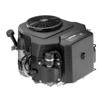
Test 3. Check for timing advance.
Figure 8-9.
3. Run the engine at idle and use the timing light
beam to locate the line on the screen. Draw a line
on the blower housing adjacent to the line on the
screen. Accelerate to full throttle and watch for
movement of the line on the screen relative to the
line on the blower housing. If both cylinders had
good spark, repeat the test on the other cylinder.
a. If the line on the screen moved away from
the line on the blower housing during
acceleration, the SAM is working properly. If
it didn’t move away, go to Test 5.
b. If you were able to check timing on both
cylinders, the lines you made on the blower
housing should be 90° apart. If they’re not,
go to Test 4.