Governor System
56 62 690 05 Rev. EKohlerEngines.com
Electronic Governor System Designs
As of this revision, there is an original design, a fi eld
installed updated design, and a new updated design.
All designs function in same manner, and both updated
designs have a non-serviceable electrical connection
with a sealed (bonded) GCU module wiring harness
assembly.
Identify design on engine being serviced and follow
those pages to diagnose and troubleshoot.
Original Design
B
D
C
A
E
B
F
A Original Design B
Governor Control Unit
(GCU)
C
Digital Linear Actuator
(DLA)
D
2 DLA Throttle Plate
Mounting Screws
E Wiring Harness F Speed Control Input
Original Design features a GCU and wiring harness
that can be separated and tested for power and ground.
This design is easily identifi ed by 2 screws that secure
DLA actuator bracket. See pages 58-64 for an engine
with original design electronic governor.
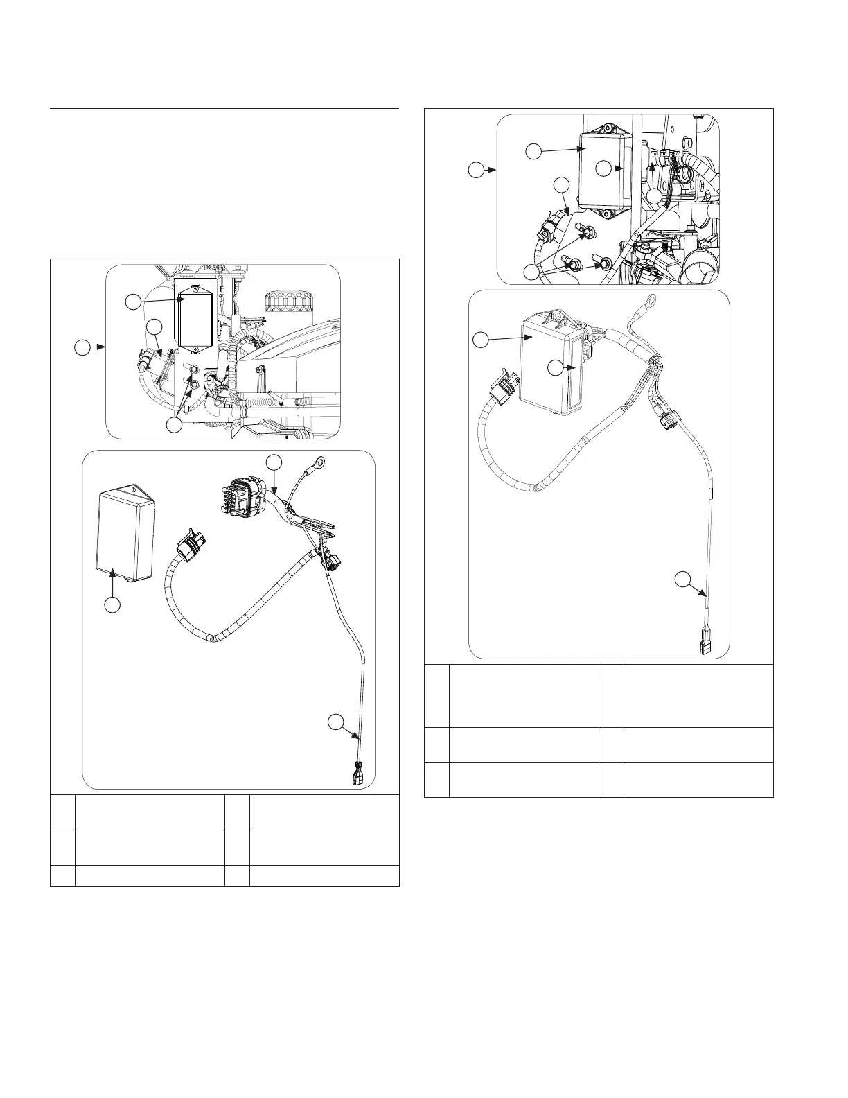
Field Installed Updated Design
This Governor Control Unit has a
Non-Serviceable Electrical Connection.
DO NOT SEPARATE
C
H
G
K
J
I
L
H
I
G
Field Installed
Updated Design
H
Sealed (Bonded) GCU
Module Wiring
Harness
Assembly
I Sealed GCU Label J
GCU Wire Tie-Down
Bracket
K
3 DLA Throttle Plate
Mounting Screws
L Speed Control Input
Field Installed Updated Design features a sealed
(bonded) GCU module wiring harness assembly that
must NOT be separated. This design is easily identifi ed
by 3 screws that secure DLA actuator bracket. This
design also has GCU wire tie-down bracket and single
Speed Control Input wire. See pages 65-71 for an
engine with fi eld installed updated design electronic
governor.