- 33 -
40
38
39
41
5
23 ÷ 25 cc 20 ÷ 22 cc (BOSCH)
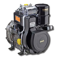
Fuel circuit
Fuel feeding can be either gravity type or forced, with a
mechanical double diaphragm pump operated a cam located on
the camshaft. Fuel is ltered by a lter in the fuel tank or through
an external lter cartridge.
The fuel circuit is bled of air automatically.
Components of gure 38:
1. Fuel tank 6. Fuel injectors
2. Fuel lter 7. Injection lines
3. Fuel supply lines 8. Fuel return lines
4. Fuel injection pumps 9. Fuel sully pump.
5. Bleed off connection
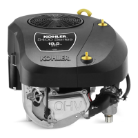
Injection pumps
Components of gure 39:
1
. Delivery connection 10. Top plate
2. O-ring 11. Retaining ring
3. Filler 12. Adjustment sleeve
4. Washer 13. Pump body
5. Valve spring 14. Sleeve securing pin
6. Delivery valve 15. Distance ring
7. Injection plunger 16. Eccentric pin
8. Lower plate 17. Cap
9. Spring 18. Clip for BOSCH pump
type PF30.
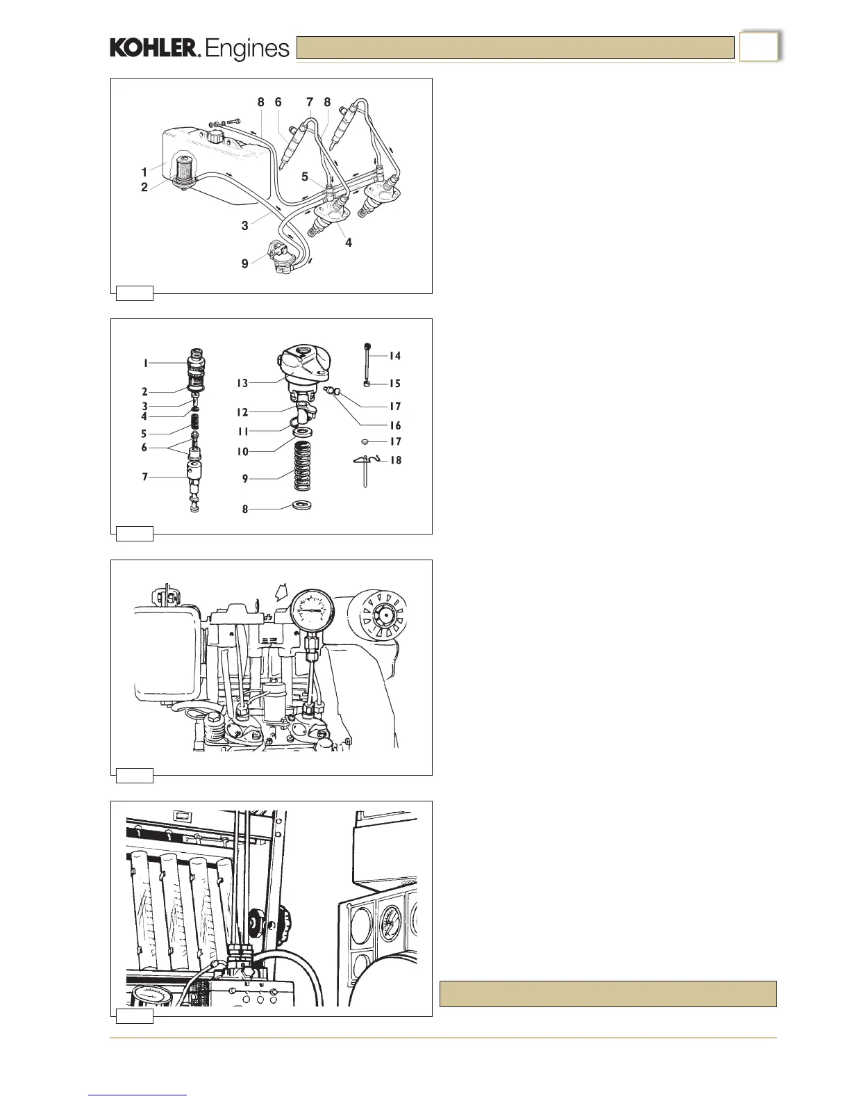
Checking injection pumps
Before dismantling the injection pumps check for pressure leak
of the pumping unit, plunger and valve, as follows:
1. Connect a pressure gauge with 600 Kg/cm² full scale to the
diesel delivery line (g.40).
2. Set the control sleeve (nr. 12, g.39) to a mid-point delivery
position.
3. Turn the ywheel slowly until the plunger has completed a
full compression stroke.
4. Take the pressure gauge reading. If it is below 300 Kg/cm²
the complete plunger unit must be changed.
During the test the reading on the gauge will show a progressive
pressure increase to a maximum value and then will fall
suddenly and stop at a lower pressure. Replace the valve if the
fall in pressure exceeds 50 Kg/cm² and continues to fall slowly.
The pressure drop from 200 Kg/cm² to 150 Kg/cm² must occur in
a time interval of no less than 7 seconds.
Injection pump setting (g.41)
Set the maximum quantity delivered by the pump by turning the
eccentric pin using a screwdriver (nr. 16, g.39).
With the control sleeve at 10mm from the stop position and the
pump running at 1,500 rpm, the quantity of fuel for 1,000 shots
must be between:
INJECTION EQUIPMENT

 Loading...