- 41 -
7
68
66
67
69
mm 36,5 ± 1
Camshaft
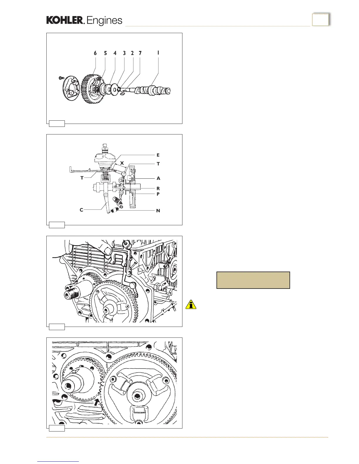
Prepare the camshaft assembly (g.66) as described below:
1. Fit adjustment shim (nr. 3) and governor washer (nr. 4) onto
the camshaft.
2. Fit snap ring (nr. 5) and key (nr. 7) into their respective
seats.
3. Preheat (180 ÷ 200 °C) gear (nr. 6) complete with yweights
and mount it to the camshaft, making sure that it is snugly
tted against the retaining ring.
4. Insert the governor driving plate retaining ring (nr. 2).
The speed governor is of the centrifugal type with yweights
keyed directly onto the end of the camshaft gear (g.67).
Flyweights (A) impelled outward by centrifugal force, cause a
moving plate (P) to shift axially. The plate operates a lever (R)
which is connected, through tie rods (T) to the control sleeves
(E) of the injection pumps.
Spring (N) placed under tension by speed control lever (C),
contrasts the action of the centrifugal force of the governor.
The balance between the two forces keeps the engine speed
virtually constant with respect to load variations.
Governor tie rod adjustment
The length of the tie rod, measured between the centredistance
of holes (X, g. 67), must be:
Important
• The accuracy of this setting will serve to eliminate hunting of
engine speed, difficulty in starting, and power fall-off.
turn
Assembly
1. Fit the tappets into their housings in the crankcase
2. Fit the governor lever and tie rod, simultaneously with the
camshaft, into the crankcase (g.68)
3. Insert the governor lever fulcrum pin from the outside of the
crankcase and secure it with the relative screw (g.68).
The lever must be free to effect its full stroke without
sticking.
4. Insert the spring between the governor lever and the
accelerator, making sure that it is correctly installed.
5.Check that the timing marks on the camshaft and crankshaft
gears are correctly aligned with respect to each other (g.
69).
Engine assembly

 Loading...