- 40 -
7
62
60
61
64
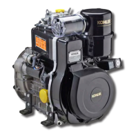
kgm 2,2 (Nm 21,6)
kgm 2,2 ÷ 2,4 (Nm 21,6 ÷ 23,5)
0,10 ÷ 0,20 mm
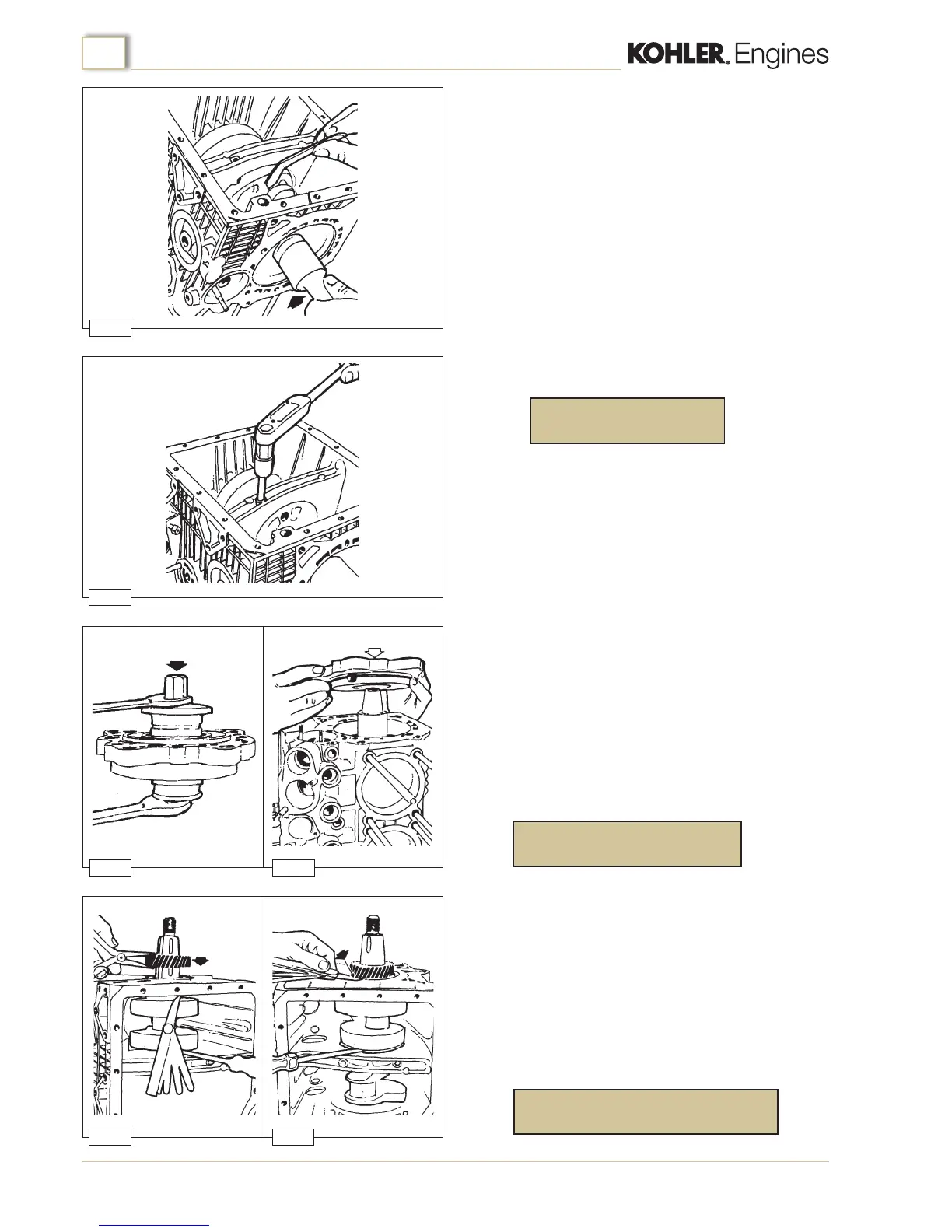
0,20 ÷ 0,30 mm
63
65
Engine assembly
(cast iron crankcase)
Crankshaft
Fit the crankshaft into the crankcase using tool p.n. 00365R0910
as shown in gure 60; make sure that the bearing oil passages
are matched to the crankcase oil passages.
Torque the bearing screws (g. 61) to :
Main bearings - ywheel side
Fit the bush to the bearing carriern using a special tool of
appropriate diameter as shown in gure 62. Insert the bush
arranging the groove so that it is facing the internal side of the
bearing and positioned vertically.
Fit the oil seal ring to the bearing using a suitable diameter
tubular punch.
Fit the bearing into the crankcase after having rst interposed an
O-ring between the contact surfaces (g. 63). Torque the screws
to:
Crankshaft end oat
Install an 0.15 mm feeler gauge betwen the crankshaft shoulder
and the crankcase (ywheel side).
Use a screwdriver to force the crankshaft against its shoulder as
shown in gure 64. Pre-heat the timing gear to a temperature of
180 ÷ 200 °C and t it onto the crankshaft pressing it down until
it comes into contact with the crankcase. Wait until the timing
gear has cooled down and then withdraw the feeler gauge and
the screwdriver and check end oat (g. 65), which must be
within the range:

 Loading...