- 45 -
80
81
7
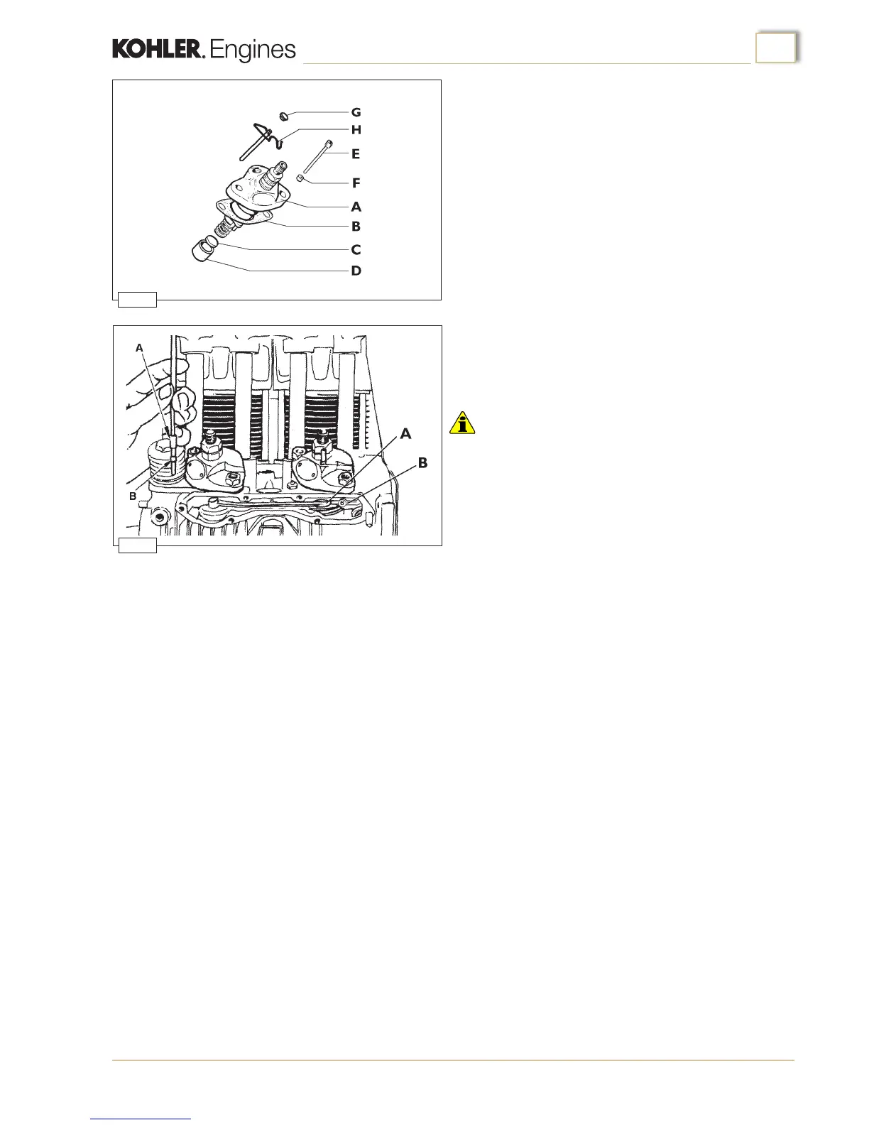
5. Release the control sleeves:
- on the traditional pumps by loosening the pins (E, g.80)
and inserting the appropriate distance collars (F, g.80).
- on the BOSCH type PF30 pumps by removing the pins (H,
g.80) and closing the hole on the pump body using plug G.
Important
• injection pumps should be released only after they have been
connected to the governor tie rod and secured to the crankcase.
If one or both pumps must be changed, in order to guarantee
the same fuel delivery for each pump the pump remaining on
the crankcase must be locked using the pins (E or H, fig.80).
Alternatively the above steps must be performed in their entirety.
Injection pumps
1
. Insert the injection pump tappet (D) and spacer (C) into the
housings in the crankcase (g.80).
2
. Assemble the injection pumps (A g. 80) on the crankcase
and secure them on the adjustment sleeve by means of the
appropriate pins (E or H g. 80) on PF30 BOSCH pumps.
Then, place the advance adjustment shims (B, g. 80)
between the crankcase and the pump.
3. Fix the injection pump connection rod (A, g.81) to the
speed governor lever tie rod (B, g.81)
4. Secure the injection pumps to the crankcase, taking care to
turn the rst injection pump around through approximately
3/4 of a turn in a clockwise direction.
Engine assembly

 Loading...