- 25 -
11
9
10
4
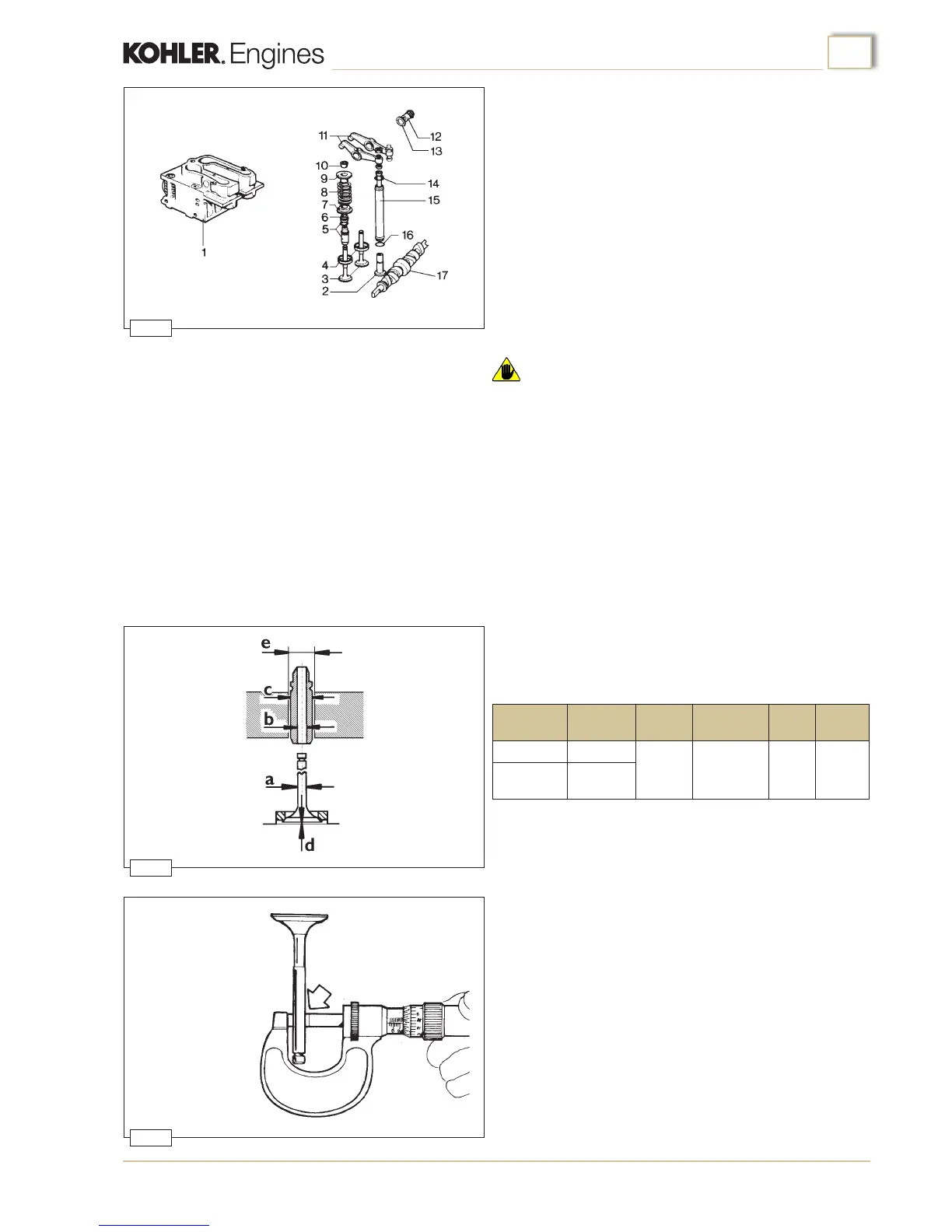
a
mm
b
mm
c
mm
d
mm
e
mm
6,960÷6,970
7,00÷7,01
13,025÷13,037 0,8÷1,0 13÷13,01
6,945÷6,955
Guide
Inlet
Exhaust
assembly
Cylinders heads
Parts shown in gure 9.
1.Head 10.Valve locking split cones
2.Tappets 11.Rocker arms
3.Valves 12.Rocker pins
4.Seats 13.Gaskets
5.Guides 14.Push rods
6.Seals 15.Cover tube
7.Lower washers 16.O-ring
8.Springs 17.Camshaft
9.Top washers
The heads are made off aluminium with valve guides and seats
are made of cast iron.
Warning
• Do not disassemble the head when the engine is hot to avoid
deformation.
Clean heads of carbon deposits and check the cylinder mating
surfaces; if they are deformed they must be ground to a maxi-
mum of 0.3 mm. Check that there are no cracks or other imper-
fections in the heads. If defects are encountered the heads must
be renewed. In this case consult the spare parts catalogue.
Valves - Guides - Seats
Clean the valves with a wire brush and renew them if the valve
heads are deformed, cracked or worn.
Check the dimensional conformity of the valve stems (g. 11)
and the clearance between valve and guide, bore out the guides
to the dimensions indicated in the table (g. 10).
Renew both guide and valve if the clearance is greater than
0.1mm.
It is always necessary to grind the valve seats when new guides
are tted.
Oversize valve guides with external diameter increased by 0.10
are available.
Checks and overhaul

 Loading...