- 30 -
30
28
29
31
4
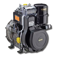
A - B 34,69 ÷ 34,74
C 34,98 ÷ 35,02
D 25,50 ÷ 25,70
0,025 ÷ 0,065
0,07 ÷ 0,105
0,04 ÷ 0,075
Checks and overhaul
Warning
• During grinding take care not to remove the shim adjustment
material from the main journal thrust face to avoid changing the
crankshaft end float; also ensure that the grinding wheel radii
are as specified in figure 28 so as not to create crack initiation
sections on the crankshaft.
Oil seal rings
Check that the rings have not hardened around the internal
contact edge and that they show no signs of cracks or wear.
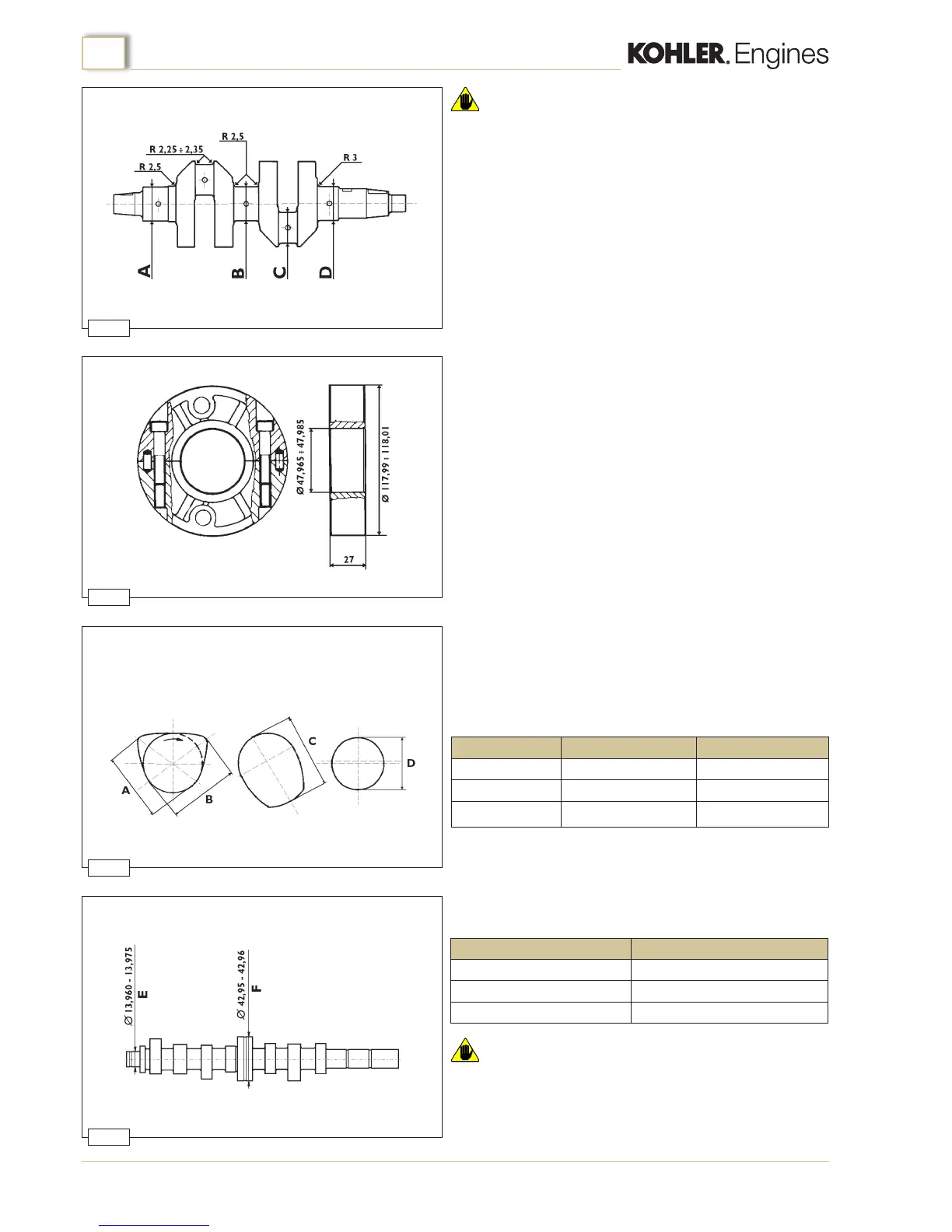
Warning
• Renew the camshaft if the cams or journals show wear in excess
of 0.1mm.
Camshaft
Check the cams and bearing journals for scoring and wear.
Measure the dimensions and compare them to the values in the
table below and shown if gures 30-31.
Camshaft dimensions g.30.
Assembly clearance between the journals and their housings
should be (g.31):
Measurement
E
F aluminium crankcase
F cast iron crankcase
Measurement Dimensions mmCam
Timing
Injection
Fuel pump
inlet/exhaust injection feeding pump
inlet/exhaust injection feeding pump
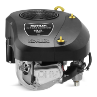
Central main bearings
In order to facilitate assembly the central main bearings are of
different external diameters (g.29) and are machined with a
bevelled edge to assist their insertion into the crankcase.
Check the dimensions of the shells and renew them if they are
worn or deformed.
Also check the condition of the oil passages, if necessary, clean
them with parafn or petrol and dry with compressed air.

 Loading...