SEN00176-02 10 Structure, function and maintenance standard
2 114E-3 Series
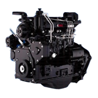
Intake, exhaust system 1
Intake system 1
General Information
1. Intake air inlet to turbocharger
2. Turbocharger air to charge air cooler
3. Charge air cooler
4. Intake manifold (integral part of cylinder head)
5. Intake valve
The combustion air system on the engine consists
of an air cleaner, intake air piping, turbocharger,
charge air piping, charge air cooler (CAC), and
intake air heater.
Air is drawn through the air cleaner and into the
compressor side of the turbocharger (1). It is then
forced through the CAC piping (2), to the CAC (3),
the intake air heater (if applicable), and into the
intake manifold (4). From the intake manifold, air is
forced into the cylinders (5) and used for combus-
tion.
 Loading...