Robertson AP11 Autopilot
66 20220513E
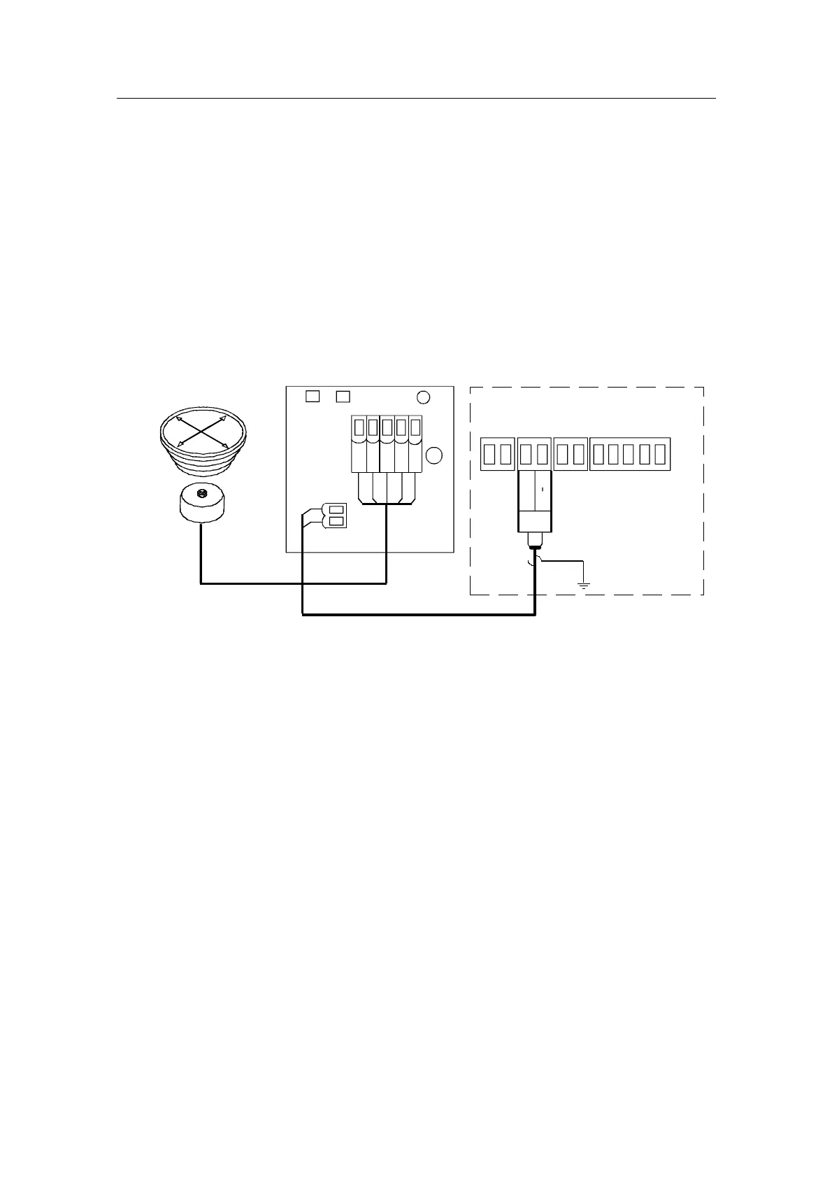
CDI35 Interface
Locate the CDI35 as close to the compass as possible so that
there will be no problem finding it in the event of a service.
Put the two fixing screws in the slots and secure the unit to
the bulkhead. Open the unit to access the screw terminals.
Cut the CD100 cable to make a suitable length and connect
both cables as shown on the diagram below.
* NON-POLARIZED
(COLOR INDEPENDENT)
JUNCTION UNIT
MAIN PCB
HS+
*
Heading
Sensor
HS
CDI35 INTERFACE PCB
BOAT'S
MAGNETIC
COMPASS
CD100
COURSE
DETECTOR
White
Brown
Green
Yellow
Grey
12
3
4
5
Figure 39 CD100/CDI35 connection
 Loading...