-
13 -
KingKORG Parameter Guide Parameters
3.
Vocoder parameters
We recommend that you edit the vocoder parameters while looking at the
vocoder block diagram (OM: p.17).
v01: Vocoder
Vocoder SW (Vocoder Switch) .................................... [Off, On]
This switches the Vocoder function on/off.
Off:
The vocoder function will be off. The front panel VOCODER button will be
unlit, and the program will not use the vocoder.
On:
The vocoder function will be on. The front panel VOCODER button will be
lit, and the program will use the vocoder. You’ll be able to select and edit
the vocoder parameter pages (“v02: Voc.Carrier” – “v18: Voc.Amp”).
v02
~
03: Voc
.
Carrier (Vocoder Carrier)
On these pages you’ll specify the input level for the carrier, the original signal
where the vocoder effect is applied.
Timb A Level (Timbre A Level) ........................................[000…127]
This specifies the output level of Timbre A (carrier).
Timb B Level (Timbre B Level) ........................................[000…127]
This specifies the output level of Timbre A.
v04
~
08: Voc.Modultr (Vocoder Modulator)
On this page you can adjust settings for the modulator, which applies its
character to the carrier audio.
As the modulator, you can input either the signal from the mic (Input) or timbre
B.
AudioSrc (Audio Source) ........................................ [Input, TimbreB]
This selects the audio source that will be sent to the modulator.
Input:
The audio source of AUDIO IN will be sent to the modulator.
TimbreB:
The output of timbre B will be input as the modulator.
Gate Sens (Gate Sensitivity)............................................[000…127]
This specifies the speed at which the gate will function according to the
“Threshold” setting.
Lower values for this setting will make the gate close more quickly, causing the
vocoder sound to decay more quickly. Higher values for this setting will make the
gate close more gradually, causing the vocoder sound to have a longer decay.
TIP:
If the Threshold value is high, this effect will apply more readily. If the Threshold value is
“000”, there will be no effect.
Threshold .........................................................................[000…127]
This sets the level at which the input source will be cut. By setting this to an
appropriate level, you can cut the noise that might be present during times
where there is no input.
TIP:
Increasing the value will make the input source more likely to be cut.
With excessively high settings, it’s more likely that the audio input signal itself will be cut,
making it difcult for you to apply the vocoder effect as intended.
HPF Level .......................................................................... [000…127]
This adjusts the output level from the HPF (High Pass Filter) that extracts the
high-frequency components from the modulator input source; these high-
frequency components are then mixed into the output of the vocoder. Increase
this value if you want to emphasize the consonants of the vocal input source.
HPF Gate ................................................................. [Disable, Enable]
The KingKORG’s vocoder can extract the high-frequency portion from the
audio source being input to the modulator, and then mix this into the output of
the vocoder. You can specify whether this high-frequency portion will be mixed
in only while the internal sound generator (Timbre A) is producing sound, or at
all times.
Osc3Ctr2 The Osc3 page Control2
Osc1Level The Mixer page Osc1Level
Osc2Level The Mixer page Osc2Level
Osc3Level The Mixer page Osc3Level
Cutoff The Filter page Cutoff
Resonance The Filter page Resonance
FcEG1Int The Filter page EG1Int
FcKeyTrk The Filter page KeyTrack
EG1Attack The EG1-Filter page Attack
EG1Decay The EG1-Filter page Decay
EG1Sustain The EG1-Filter page Sustain
EG1Release The EG1-Filter page Release
EG2Attack The EG2-Amp page Attack
EG2Decay The EG2-Amp page Decay
EG2Sustain The EG2-Amp page Sustain
EG2Release The EG2-Amp page Release
LFO1Freq The LFO1 page Freq.
LFO2Freq The LFO2 page Freq.
AmpLevel The Amp page Level
Panpot The Amp page Pan
Patch1Int The V.Patch1 page Int
Patch2Int The V.Patch2 page Int
Patch3Int The V.Patch3 page Int
Patch4Int The V.Patch4 page Int
Patch5Int The V.Patch5 page Int
Patch6Int The V.Patch6 page Int
Pre Drive DRIVE/FREQ knob of PRE FX
Mod Depth DEPTH knob of MOD FX
Mod Speed SPEED knob of MOD FX
R/D Depth DEPTH knob of REV/DELAY
R/D Time TIME knob of REV/DELAY
Int (Intensity) ...................................................................[–63…+63]
Specifies the depth of the effect produced by the modulation source. With a
setting of “+00”, there will be no modulation.
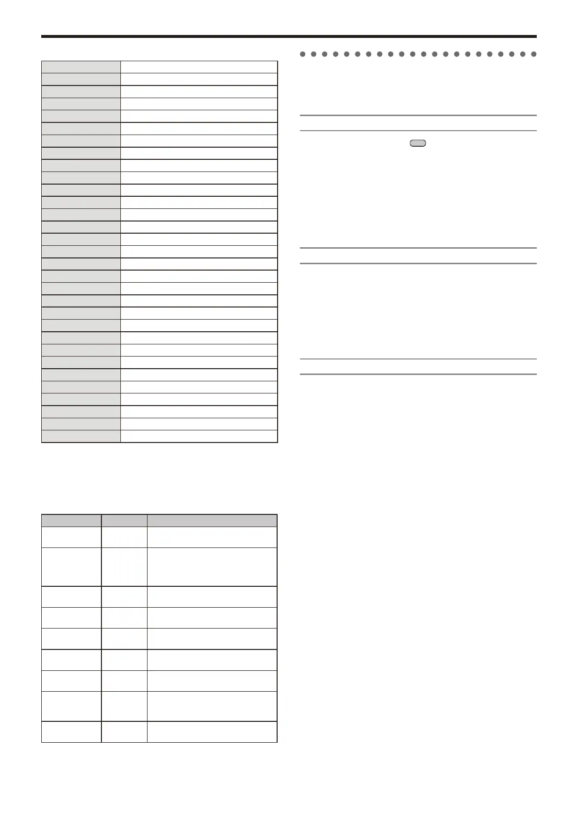
Setting example for “SOURCE” and “DEST”
Src Dest
EG1/EG2 Pitch The EG1 or EG2 will vary the pitch of
the entire timbre over time.
EG1/EG2 Panpot
The EG1 or EG2 will vary the pan over
time. By setting two patches to Patch#Int
settings with the opposite (+/–) value you
can create more complex panning.
LFO1/LFO2 Pitch Vibrato will apply at the rate of LFO1 or
LFO2.
LFO1/LFO2 Cutoff Wah will be applied at the LFO1 or
LFO2 frequency.
LFO1/LFO2 AmpLevel Tremolo will be applied at the LFO1 or
LFO2 frequency.
LFO1/LFO2 Panpot Auto pan will be applied at the LFO1 or
LFO2 frequency.
Velocity AmpLevel Velocity (keyboard playing strength) will
affect the volume.
KeyTrack Panpot Keyboard position will gradually change
the pan; lower notes at the left, and
higher notes at the right.
PitchBend Panpot Joystick operation will move the sound
left or right.