-
35 -
KingKORG Parameter Guide
MIDI
6.
Default control change
assignments and transmission/
reception (CC#Map)
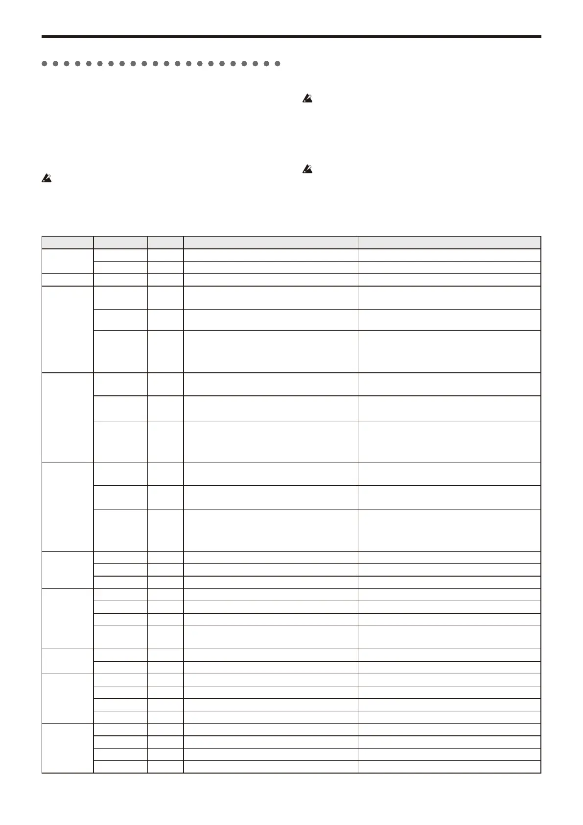
The table below shows the default assignments of the control changes that
can be assigned by the CC#Map function, and lists the values that are
transmitted and received for each parameter.
TIP:
You can make CC#Map assignments in the GLOBAL “g28: MIDI CC#Map (→ p.19).
TIP:
These messages are transmitted and received on the global channel.
If you are using two KingKORG units to transmit and receive these
parameters, you must set the transmitting and receiving programs to the
same settings.
Transmission
Using the KingKORG’s knobs or buttons will transmit the control change
messages that are assigned to those parameters.
Control changes will not be transmitted when you use the knobs and
buttons while editing a program.
Reception
When a control change message is received, the value of the assigned
parameter will change.
If you’re using timbre B, timbres A and B will be changed simultaneously.
If the MIDI channel of timbre B (→ p.4) is different than the global
channel, the parameter of timbre B will not be.
Section Parameter Assign Value (transmitted) Value (received)
Pitch
Porta.Time CC#005 0…127 0…127
Portamento CC#065 0:Off, 127:On 0…63:Off, 64…127:On
Voice Unison Voice CC#003 0: Off, 32:2, 64:3, 96:4 0…31: Off, 32…63: 2, 64…95: 3, 96…127: 4
Osc1
Type CC#008
0: Off, 1…32: ANALOG, 33…96: DWGS,
97…126: PCM, 127: MIC IN
0: Off, 1…32:ANALOG, 33…96: DWGS, 97…126:PCM,
127: MIC IN
CONTROL 1 CC#015 0…127
0…127 (when using the dual, ring, or mic-in oscillators,
0/1: –63, 2: –62…63: –01, 64: +00, 65: +01…127: +63)
CONTROL 2 CC#017 0…127
(when using the cross modulation oscillator, 0/1: –63,
2: –62...63: –01, 64: +00, 65: +01...127: +63)
(→ p.37 “Mod Harm values for VPM oscillators OSC1, 2,
and 3”)
Osc2
Type CC#018
0: Off, 1…32: ANALOG, 33…96: DWGS, 97…126: PCM,
127: MIC IN
0: Off, 1…32: ANALOG, 33…96: DWGS, 97…126: PCM,
127: MIC IN
CONTROL 1 CC#019 0…127
0...127 (when using the dual, ring, or mic-in oscillators,
0/1: –63, 2: –62...63: –01, 64: +00, 65: +01...127: +63)
CONTROL 2 CC#020 0…127
0...127 (when using the cross modulation oscillator,
0/1: –63,2: –62...63: –01, 64: +00, 65: +01...127: +63)
(→ p.37 “Mod Harm values for VPM oscillators OSC1, 2,
and 3”)
Osc3
Type OFF
0: Off, 1…32: ANALOG, 33…96: DWGS, 97…126: PCM,
127: MIC IN
0: Off, 1…32: ANALOG, 33…96: DWGS, 97…126: PCM,
127: MIC IN
CONTROL 1 OFF 0…127
0…127(when using the dual, ring, or mic-in oscillators,
0/1: –63, 2: –62…63: –01, 64: +00, 65: +01…127: +63)
CONTROL 2 OFF 0…127
0...127 (when using the cross modulation oscillator,
0/1: –63,2: –62...63: –01, 64: +00, 65: +01...127: +63)
(→ p.37 “Mod Harm values for VPM oscillators OSC1, 2,
and 3”)
Mixer
OSC1Level CC#023 0…127 0…127
OSC2Level CC#024 0…127 0…127
OSC3Level CC#025 0…127 0…127
Filter
Cutoff CC#074 0…127 0…127
Resonance CC#071 0…127 0…127
EG1 Int CC#079 0/1: –63, 2: –62…63: –01, 64: +00, 65:+01…127: +63 0/1: –63, 2: –62…63: –01, 64: +00, 65: +01…127: +63
KeyTrack CC#028
0/1: –2.00 2: -1.93…63: –0.02, 64: +0.00,
65: +0.02…127: +2.00
0/1: –2.00 2: -1.93…63: –0.02, 64: +0.00,
65: +0.02…127: +2.00
Amp
Level CC#007 0…127 0…127
Pan CC#010 Not transmitted 0/1: L63, 2: L62…63: L01, 64: Center, 65: R01…127: R63
EG1-Filter
Attack CC#085 0…127 0…127
Decay CC#086 0…127 0…127
Sustain CC#087 0…127 0…127
Release CC#088 0…127 0…127
EG2-Amp
Attack CC#073 0…127 0…127
Decay CC#075 0…127 0…127
Sustain CC#070 0…127 0…127
Release CC#072 0…127 0…127