-
8 -
KingKORG Parameter Guide Parameters
029: VPM Saw
Outputs a modulated sawtooth wave.
030: VPM Square
Outputs a modulated square wave.
031: VPM Tri.
Outputs a modulates triangle wave.
032: VPM Sine
Outputs a modulated sine wave.
CONTROL1: Mod Depth ...............................................[000...127]
This adjusts the depth of the VPM (Variable Phase Modulation) effect.
CONTROL2: Mod Harm(Mod Harmonics) .................. [0.5, 1...32]
This specifies the pitch of oscillator B (modulator) as a harmonic multiple of
oscillator A (carrier).
DWGS oscillator
Detune
Mod Depth
DWGS A
DWGS B
These oscillator types produce the simple DWGS (Digital Waveform Generator
System) waveforms found on digital synthesizers such as the Korg DW-8000.
You can generate complex overtones by using VPM (Variable Phase
Modulation) to modulate the waveform.
033
-
096: DWGS
These are DWGS waveforms from digital synthesizers.
CONTROL1: Detune ...................................................... [000...127]
Detunes the relative pitch of the two DWGS oscillators.
Higher values will broaden the pitch difference, creating modulation that makes
the sound richer.
CONTROL2: Mod Depth ..............................................[000…127]
Adjusts the depth of the VPM effect for the DWGS waveform.
PCM oscillator
These oscillator types produce PCM waveforms of acoustic instruments or
digital synthesizers.
097
-
126: PCM
These are PCM waveforms of acoustic instruments and digital synthesizers.
If you’ve selected a PCM oscillator, CONTROL 1 and CONTROL 2 are
not available.
MIC IN oscillator
Gain
Mic Input
This lets you use the signal from the rear panel mic jack as the oscillator
waveform.
You can apply the filter, amp, and effects to this audio signal.
If you’re using the audio input from the mic jack, pitch-related parameters
are not available.
If you’ve selected the MIC IN oscillator, CONTROL 2 is not available.
127: Mic In
Outputs the signal from the rear panel mic jack.
CONTROL1: Gain .........................................................[–63…+63]
This adjusts the level of the signal from the mic jack.
At a value of “+00” the input signal will be unchanged (Unity Gain).
If the peak LED lights up, you should also adjust the front panel MIC
LEVEL knob until the signal is no longer peaking.
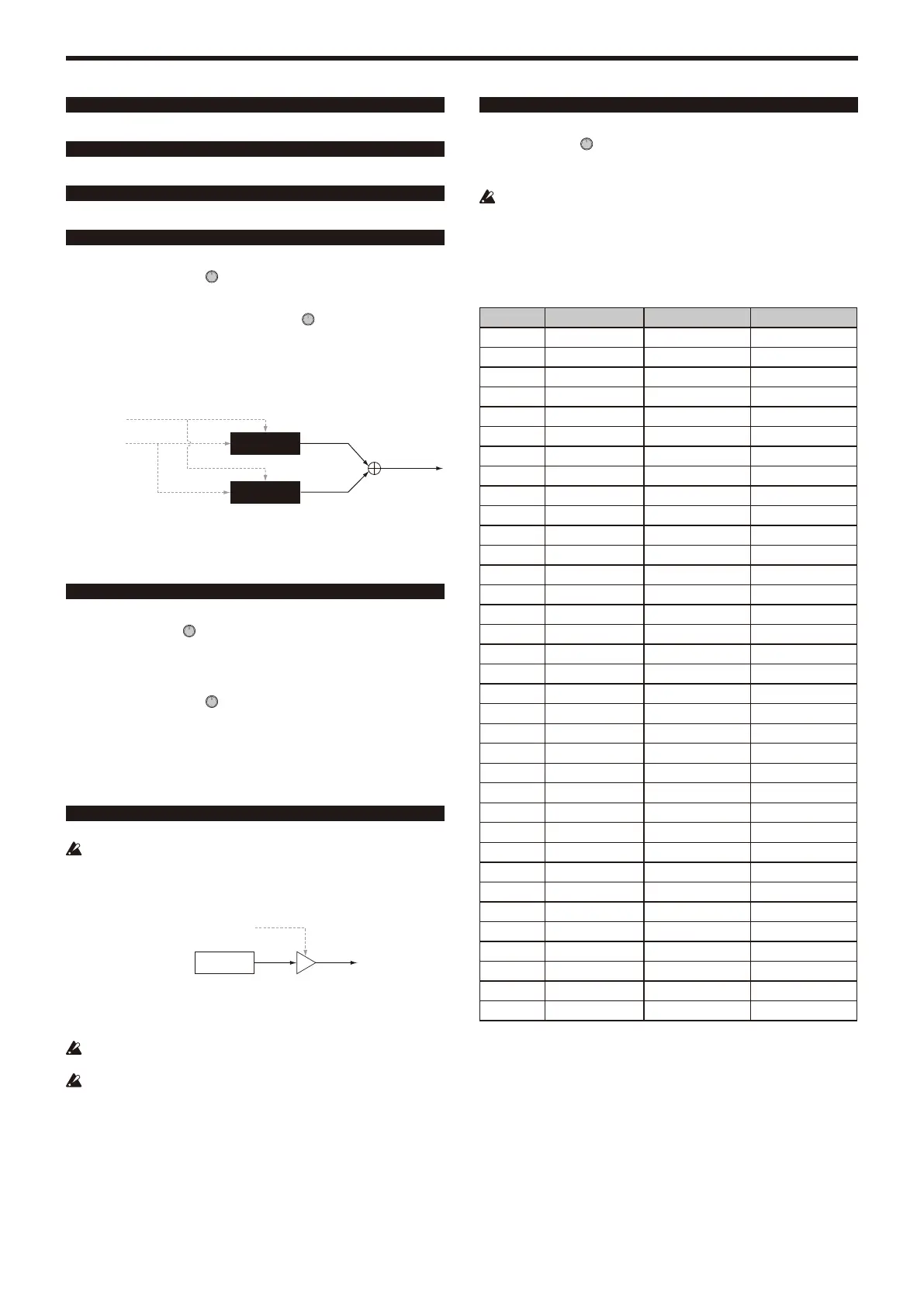
Oscillator list
Oscillator types 001–032 are excellent analog modeling oscillators. When you
select one of these, the ANALOG LED will light up below the OSCILLATOR
sub-display.
No. Type Control1 Control2
001 Saw Waveform —
002 Pulse PulseWidth —
003 Triangle Waveform —
004 Sine Waveform —
005 White Noise Decimator Fc Noise Decay
006 Pink Noise LPF Cutoff Noise Decay
007 Blue Noise HPF Cutoff Noise Decay
008 Res. Noise Resonance Noise Decay
009 Dual Saw Detune —
010 Dual Square Detune —
011 Dual Tri. Detune —
012 Dual Sine Detune —
013 Unison Saw Detune —
014 Unison Squ. Detune —
015 Unison Tri. Detune —
016 Unison Sine Detune —
017 Sync Saw Mod Pitch —
018 Sync Square Mod Pitch —
019 Sync Tri. Mod Pitch —
020 Sync Sine Mod Pitch —
021 Ring Saw Mod Pitch —
022 Ring Square Mod Pitch —
023 Ring Tri. Mod Pitch —
024 Ring Sine Mod Pitch —
025 XMod Saw Mod Depth Mod Pitch
026 XMod Square Mod Depth Mod Pitch
027 XMod Tri. Mod Depth Mod Pitch
028 XMod Sine Mod Depth Mod Pitch
029 VPM Saw Mod Depth Mod Harm
030 VPM Square Mod Depth Mod Harm
031 VPM Tri. Mod Depth Mod Harm
032 VPM Sine Mod Depth Mod Harm
033–096
DWGS Detune Mod Depth
097–126
PCM — —
127 Mic In Gain —