Shenzhen Anycubic Technology Co., Ltd.
10
6. Extrusion system
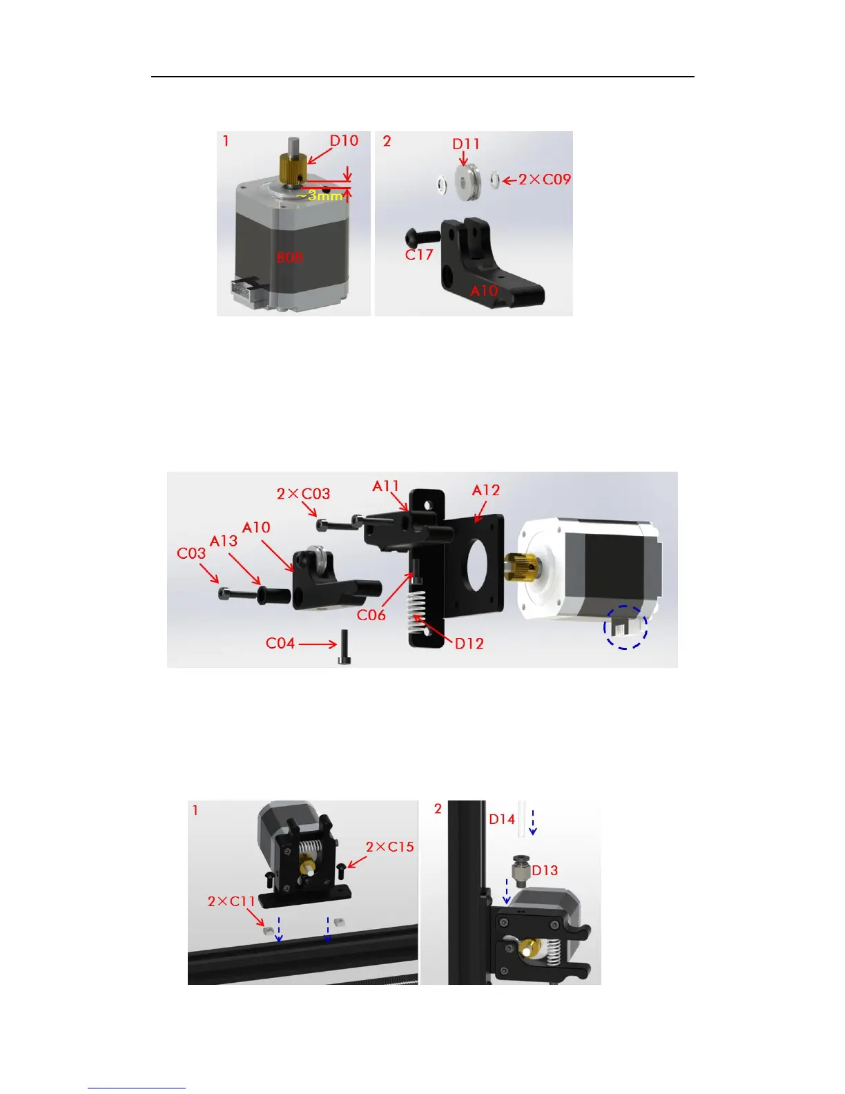
Fig. 22
Step 1. As shown in Fig. 22, firstly fix the extrusion wheel (D10) onto the shaft of the
extrusion motor (B08). Make sure the fastening screw is facing the plane of the shaft. Notice
the distance between the extrusion wheel and the motor is about 3mm. Next, install the
extrusion bearing with 2 washers onto the bearing holder as shown on the right of Fig. 22.
Step 2. The assembly details (from right to left) of the extruder are shown in Fig. 23. The
socket of the extrusion motor is suggested to face down (blue dash circle).
Fig. 23
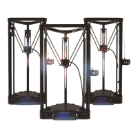
Step 3. As shown in Fig. 24, lie down the main frame and choose one of the 3 long
Al-extrusions to fix the extruder on by using 2 pairs of C15 and C11. The position of the
extruder should be a bit lower from the middle, which could be seen in the cover page. Next,
find the quick connector (D13) and the feeding pipe (D14) and fix them onto extruder.
Fig. 24