Shenzhen Anycubic Technology Co., Ltd.
8
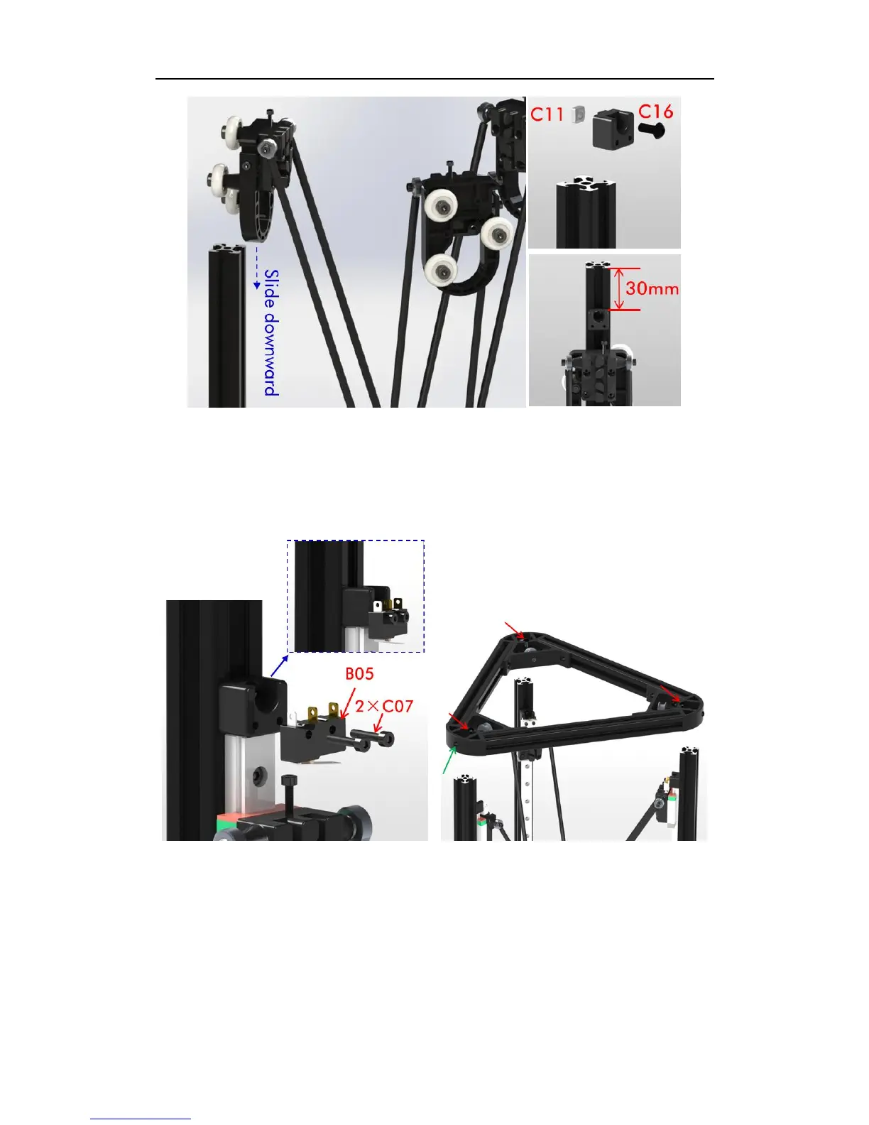
Fig 17
4. Main frame
The assembly of main frame and limit switches is the same for both Linear and Pulley
version. Here we take Linear version for example.
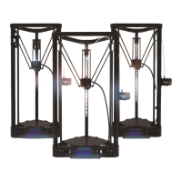
Step 1. Fix the limit switches (B05) to each of the stop blocks as shown in Fig. 18.
Fig. 18 Fig. 19
Step 2. As shown in Fig. 19, install the top triangle frame to the main structure. Meanwhile
adjust the screws (red arrows) to level the upper surface of the triangle frame with the top of
each Al-extrusion. Fasten the 3 screws on the side (green arrow) after leveling.
Step 3. Install one end of the wire (B06) to the limit switch through the top triangle frame (no
positive and negative). Lead the other end of the wire passing through the hole of the
Al-extrusion and the holes of the bottom triangle, which is shown in Fig. 20. After that, fix