DSP-62-AEC, DSP-62-UC – Mounting the Device
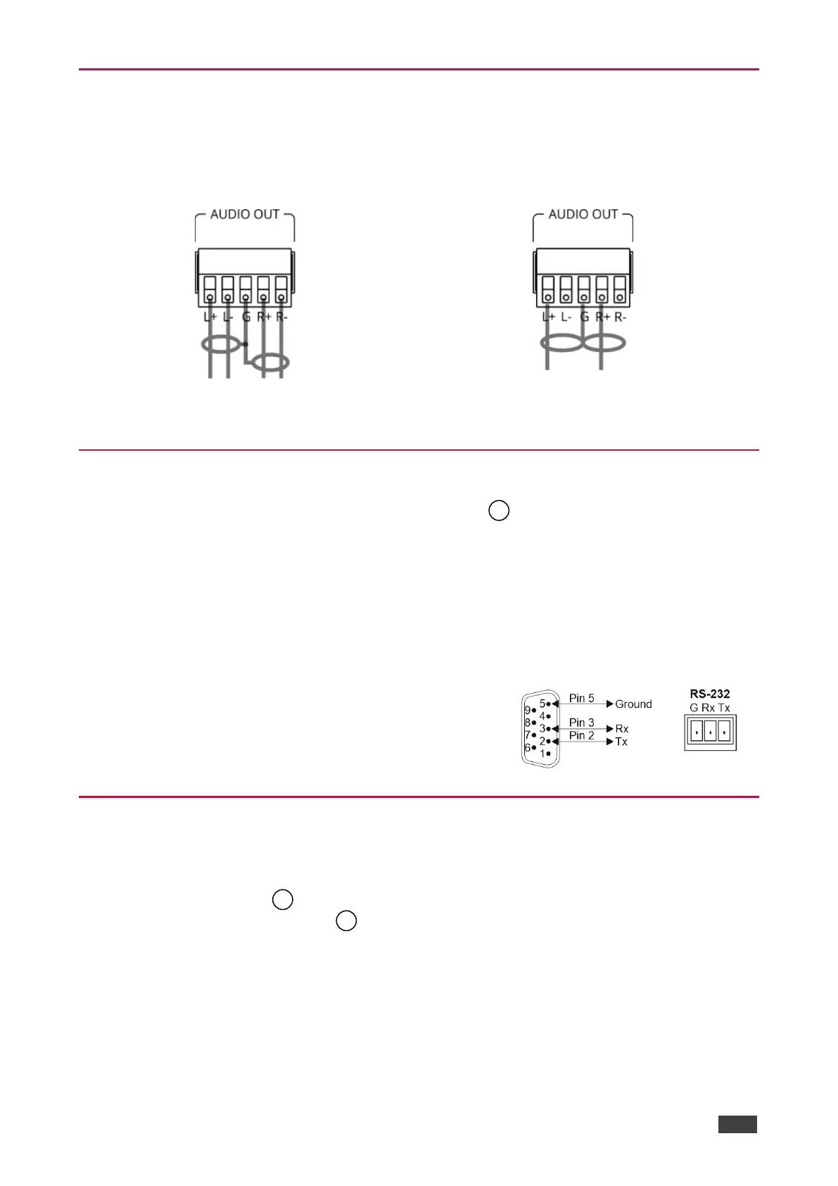
Connecting the Output to a Balanced/Unbalanced
Stereo Audio Acceptor
The following are the pinouts for connecting the output to a balanced or unbalanced stereo
audio acceptor:
Figure 7: Connecting to a Balanced Stereo Audio
Acceptor
Figure 8: Connecting to an Unbalanced Stereo Audio
Acceptor
Connecting to the Device via RS-232
You can connect the device via an RS-232 connection using, for example, a PC.
DSP-62 a RS-232 3-pin terminal block connector that allows the RS-232 to control the device.
Connect the RS-232 terminal block on the rear panel of the device to a PC/controller as
follows:
From the RS-232 9-pin D-sub serial port connect:
• Pin 2 to the TX pin on the DSP-62 RS-232 terminal block.
• Pin 3 to the RX pin on the DSP-62 RS-232 terminal block.
• Pin 5 to the G pin on the DSP-62 RS-232 terminal block.
Operating the DSP-62-AEC, DSP-62-UC
DSP-62-AEC, DSP-62-UC include two front panel buttons (HDMI IN 1 and HDMI IN 2) to
select the input, and indication LEDs to indicate signal presence:
• One USB IN LED to indicate that an audio source is received from the USB host port
(green) and one USB OUT LED to indicate that an audio signal is sent to an
acceptor.
• 5 Audio IN LEDs to indicate that a signal is present (green), clipping is detected (red),
and for LEDs 2 to 5, that a microphone is connected (blue).
• One AUDIO OUT LED to indicate that a signal is present (green), or clipping is detected
(red).