SID-X1N - Remote Commands 27
4th Byte: Bit 7 – Defined as 1
Bit 5 – Don’t care
OVR – Machine number override
M4…M0 – MACHINE NUMBER
This byte is used to address machines in a system by their machine numbers. When several machines are controlled
from a single serial port, they are usually configured together and each machine has an individual machine number. If
the OVR bit is set, then all machine numbers accept (implement) the command and the addressed machine replies.
When a single machine is controlled over the serial port, always set M4…M0 to 1, and make sure that the machine itself
is configured as MACHINE NUMBER = 1.
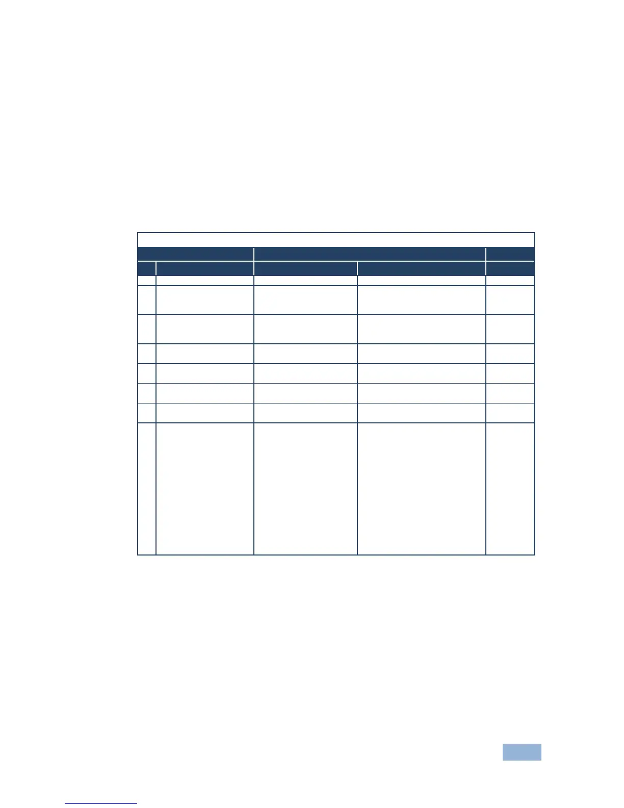
12.2 Kramer Protocol 2000 Instruction Codes
All the values in the table are decimal, unless otherwise stated
Instruction Codes for Commands
Definition for Specific Instruction
Set equal to video output that is
Set equal to audio output that is
REQUEST STATUS OF
A VIDEO OUTPUT
Equal to output number whose
status is required
REQUEST STATUS OF
AN AUDIO OUTPUT
Equal to output number whose
status is required
OUTPUT byte = 6;
OR
Set as output # when
OUTPUT byte = 7;
OR
Set as blank period
(in steps of 25ms) when
OUTPUT byte = 32;
OR
Set = 0. *****
1 – Input # 1
2 – External digital sync
3 – External analog sync
4 – Dynamic sync
5 – Inter-machine sync
6 – Input # (INPUT byte)
7 – Output #(INPUT byte)
8 – User-defined sync
32 – RGBHV seamless switching
64 – Set for delayed switch
65 – Execute delayed switch
66 – Cancel delayed switch
NOTES on the above table:
NOTE 2 – These are bi-directional definitions. If the switcher receives the code, it performs the instruction. If
the instruction is performed (due to a keystroke operation on the front panel), then these codes are sent.
For example, if the PC sends HEX code:
01 85 88 83
then the switcher (machine 3) switches input 5 to output 8.
If the user switches input 1 to output 7 using the front panel buttons, the switcher sends HEX code:
41 81 87 83
to the PC.
When the PC sends one of the commands in this group to the switcher, if the instruction is valid, the switcher
replies by sending the same four bytes to the PC that it received (except for the first byte, where the
DESTINATION bit is set high).
NOTE 5 – For the OUTPUT byte set as 6, the VIS source is the input selected using the OUTPUT byte.
Similarly, for the OUTPUT byte set as 7, the VIS source is the output selected using the OUTPUT byte. Note
that on some machines the sync source is not software selectable, but is selected using switches, jumpers,
etc.