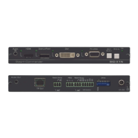
26 SID-X1N - Remote Commands
12 Remote Commands
Note: The SID-X1N can be controlled remotely only via DGKat, for example from
the VP-81SID or TP-574, using Kramer Protocol 2000 remote commands.
This protocol uses four bytes of information as defined below. The default data
rate is 9600 baud, with no parity, 8 data bits and 1 stop bit.
This section describes:
• Kramer Protocol 2000 syntax (see Section 12.1
)
• Kramer Protocol 2000 instruction codes (see Section 12.2)
• RS-232 hardware interface (see Section 12.3)
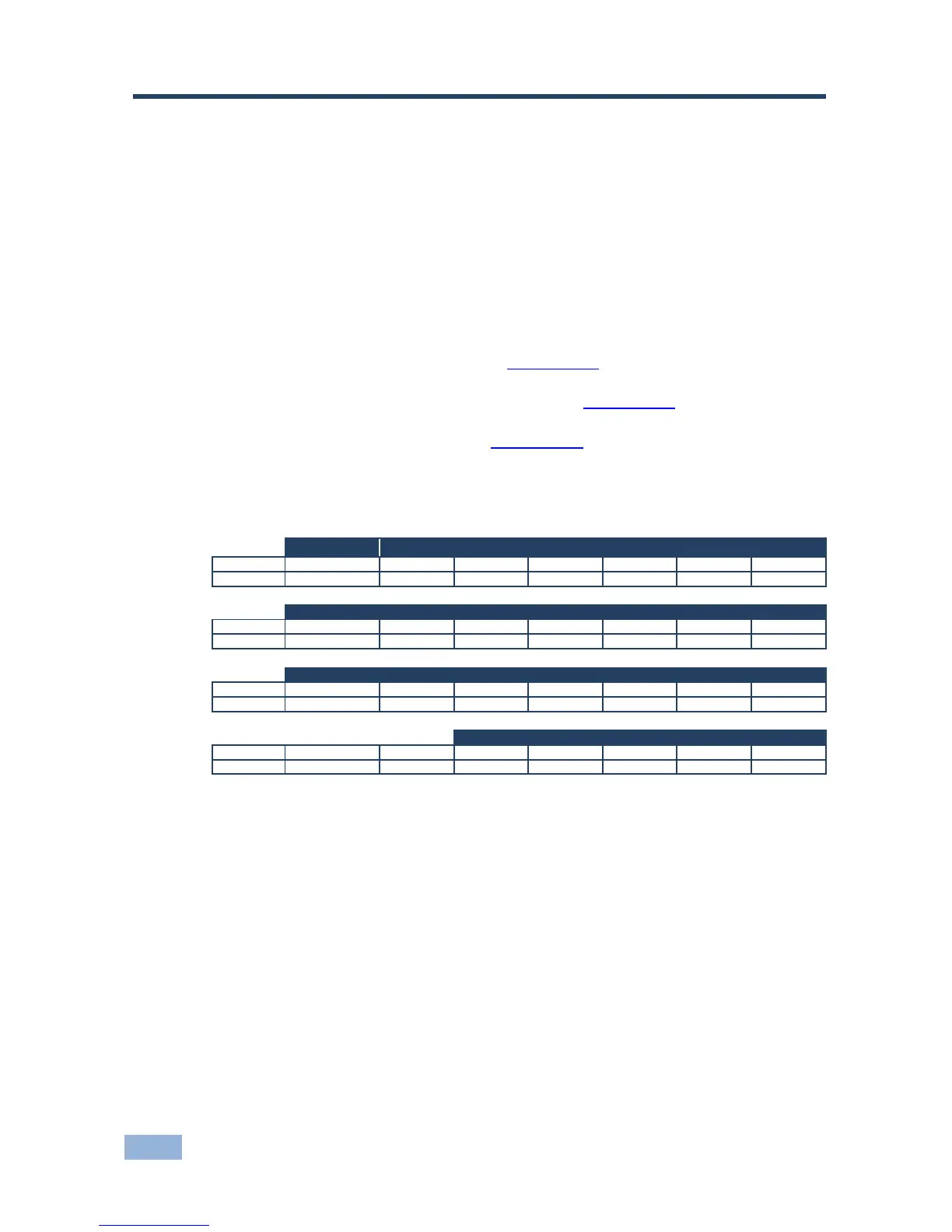
12.1 Kramer Protocol 2000 Syntax
1st Byte: Bit 7 – Defined as 0
D – DESTINATION:
0 – Sends information to the switchers (from the PC)
1 – Sends information to the PC (from the switcher)
N5…N0 – INSTRUCTION
The 6-bit INSTRUCTION defines the function performed by the switcher(s). If a function is performed using the
machine’s keyboard, these bits are set with the INSTRUCTION NO. performed. The instruction codes are defined
according to the table below (INSTRUCTION NO. is the value set in N5…N0).
2nd Byte: Bit 7 – Defined as 1
I6…I0 – INPUT
When switching (i.e. instruction codes 1 and 2), the 7-bit INPUT is set as the input number to be switched. If switching is
done using the machine’s front panel, these bits are set with the INPUT NUMBER switched. For other operations, these
bits are defined according to the table.
3rd Byte: Bit 7 – Defined as 1
O6…O0 – OUTPUT
When switching (i.e. instruction codes 1 and 2), the 7-bit OUTPUT is set as the output number to be switched. If
switching is done using the machine’s front panel, these bits are set with the OUTPUT NUMBER switched. For other
operations, these bits are defined according to the table.