SID-X1N - Defining the SID-X1N Step-in Commander 7
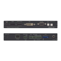
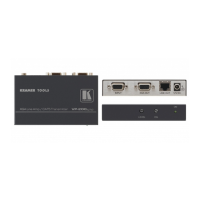
Figure 2 defines the rear panel of the SID-X1N.
Figure 2: SID-X1N Step-in Commander Rear Panel
1 AUDIO OUT 3.5mm Mini Jack Connect to an unbalanced, stereo audio acceptor, (see
2 TP OUT RJ-45 Connector Connect to a compatible switcher or DGKat receiver, (for
example, VP-81SIDN or PT-572+) using CAT 6 or higher
Connect to the anode of the remote Step-In LED indicator
Connect to the remote, Step-In switch, (see Section 5.1)
RS-232 3-pin Terminal
Block
Connect to the PC via RS-232 to perform a firmware upgrade
REMOTE
SELECT 8-pin
Terminal Block
Connect to the anode of the remote Input Select LED indicator,
(see Section 4)
Connect to the remote, Input Select switch, (see Section 5.2)
8 LED HDMI,
DP, DVI
and UXGA
Connect to the anodes of the remote input indicators
(see Section 5.3
)
Sets the device behavior, (see Section 8.1)
Connect to the supplied power adapter, center pin positive