SID-X1N – Contents i
Contents
1 Introduction 1
2 Getting Started 2
2.1 Achieving the Best Performance 2
2.2 Safety Instructions 2
2.3 About the Power Connect Plus™ Feature 3
2.4 Shielded Twisted Pair/Unshielded Twisted Pair 3
2.5 Recycling Kramer Products 3
3 Overview 4
4 Defining the SID-X1N Step-in Commander 6
5 Connecting the SID-X1N 8
5.1 Connecting the Remote Step-In Switch and LED 9
5.2 Connecting the Remote Select Switch and LED 10
5.3 Connecting the Remote Input Selection LEDs 11
6 Principles of Operation 12
6.1 Video Input Selection 12
6.2 Audio Signal Control 13
6.3 Automatic Output Shutdown 13
7 Operating the SID-X1N 14
7.1 Manually Selecting an Input 14
7.2 Taking Control of the Switcher Input 15
7.3 Locking the EDID 15
7.4 Adjusting the UXGA Input Phase 15
8 Configuring and Maintaining the SID-X1N 16
8.1 Setting the Configuration DIP-switch 16
9 Wiring the Twisted Pair RJ-45 Connectors 18
10 Technical Specifications 19
10.1 Supported Resolutions 20
11 Default EDID 22
11.1 HDMI, DisplayPort and DVI 22
11.2 PC-UXGA 24
12 Remote Commands 26
12.1 Kramer Protocol 2000 Syntax 26
12.2 Kramer Protocol 2000 Instruction Codes 27
12.3 RS-232 Hardware Interface 28
Figures
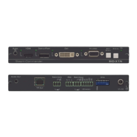
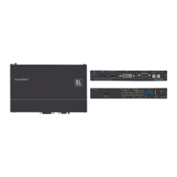
Figure 1: SID-X1N Step-in Commander Front Panel 6
Figure 2: SID-X1N Step-in Commander Rear Panel 7
Figure 3: Connecting the SID-X1N Step-in Commander 8
Figure 4: Remote Step-In Switch and LED Wiring 9
Figure 5: Remote Select Switch and LED Wiring 10
Figure 6: Remote Input Indicator LED Connections 11
Figure 7: Remote Input Indicator LED Wiring 11
Figure 8: The Configuration DIP-switch 16
Figure 9: TP Pinout Wiring 18