Page | 9
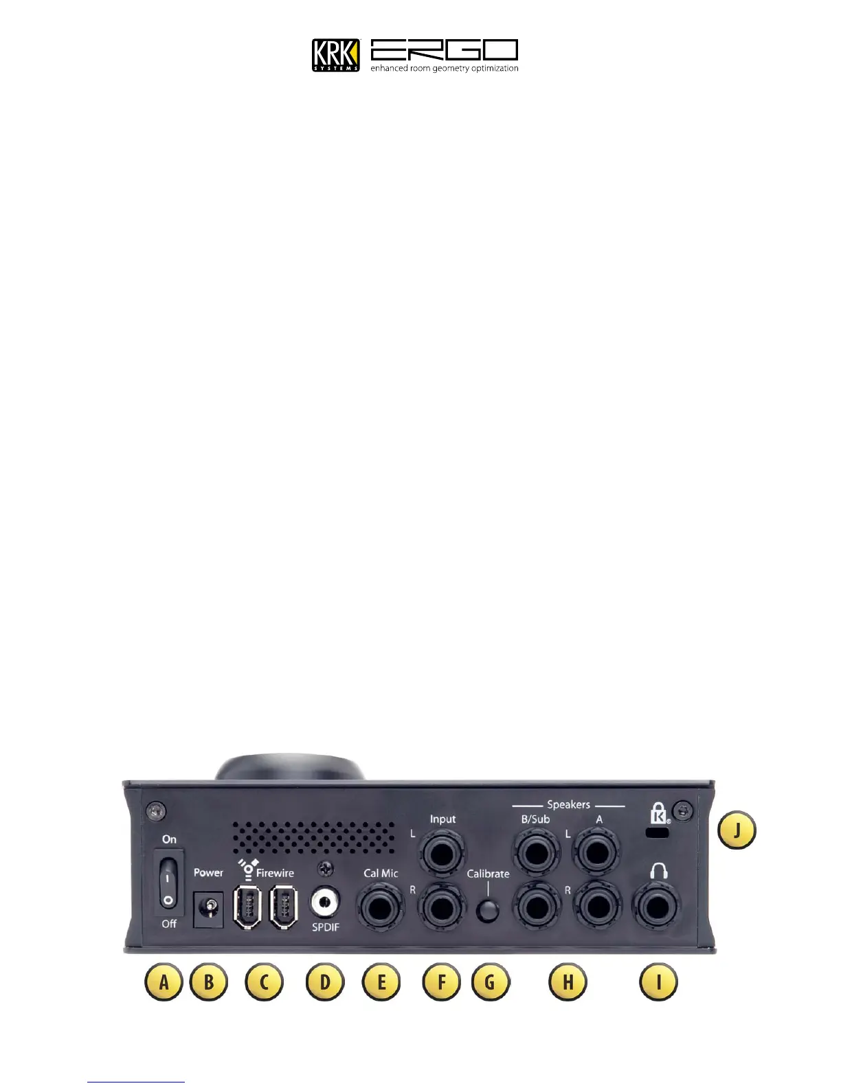
7. Back Panel Connections
Power On Switch – This turns the unit on/off.
A.
Power Input Socket – This accepts a 12V/1A input from the power supply included with ERGO.
B.
Firewire Ports - These 2 ports allow connection and daisy chaining of FireWire devices.
C.
S/PDIF Digital Input – This allows connection of a digital input source from a playback device or another
D.
audio interface.
Calibration Microphone Input - This jack is used to connect the ERGO measurement microphone. It is
E.
only used during the calibration process. It is recommended that you only use the microphone supplied
with ERGO for room calibration. ERGO supplies a 15V phantom power source to its microphone, and using
other microphones for calibration may result in poor room analysis and improper correction filters.
Balanced ¼” TRS Analog Line Inputs – These connections are used either as inputs from your existing
F.
audio interface or as recording inputs from a mixer, or rack channel.
Calibrate Button – This requires switching manually during the calibration process, you will be told when
G.
to engage and disengage it.
Balanced ¼” TRS Analog Line Outputs – These connections are used to connect to your monitoring
H.
system. Dual monitor systems can be connected to A/B, or 2.1 systems with subwoofers can be connected
to A+B.
Headphones Output – Headphones can be connected here to monitor the signal being sent to your
I.
monitors, or as an individual Solo/Cue feed.
Kensington™ Security Lock – Used to secure the unit via a Kensington Security Device (purchased
J.
separately if required)