4
OPERATION
12
OPTIMASS 6400
www.krohne.com 11/2017 - 4004960802 - AD OPTIMASS 6400 SIL R02 en
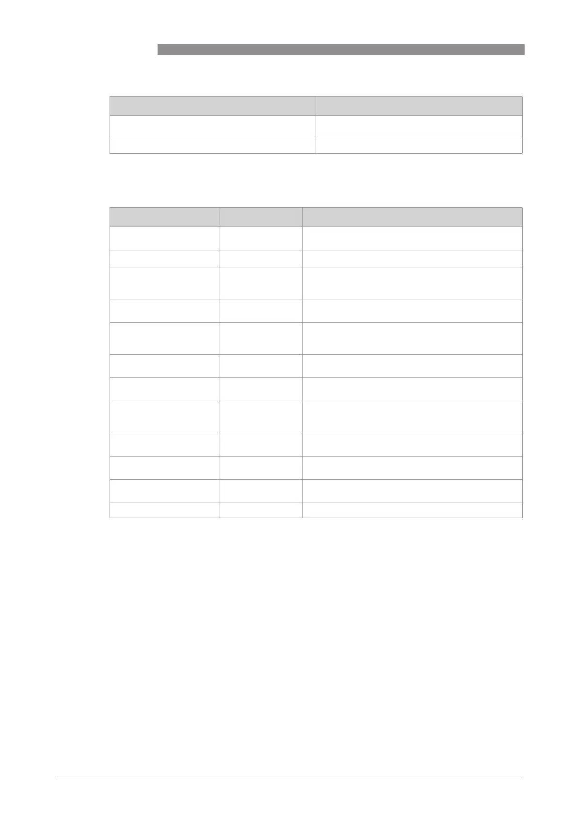
Following parameters must be configured for safe operation of the device (menu C7.1):
Changeable safety relevant parameters in safe configuration
Simulation functions for mass flow, volume flow,
density and temperature
disabled
Simulation function for safe current output disabled
Parameter Values Description
Safety Mode non-SIL Mode
SIL Mode
Safety mode of the device
Device Tag 8 characters
Device tag for identification of device via HART
®
Measurement Mass Flow
Volume Flow
Density
Device variable which is assigned to the safe current
output
Lower Range Depends on device
variable
Lower range value for safe current output (4 mA)
Upper Range Depends on device
variable
Upper range value for safe current output (20 mA).
The upper range value must be bigger than the lower
range value
Alarm Code Low = 3.5 mA
High = 21.5 mA
Preferred failure current
Low Flow Cutoff
(Threshold)
0%...20% Low flow cutoff threshold at safe current output
referred to upper range value
Low Flow Cutoff
(Hysteresis)
0%...20% Low flow cutoff hysteresis at safe current output
referred to upper range value. The hysteresis must be
smaller than the threshold.
Damping 0...100 s Damping for safe current output device variable.
This parameter affects the process response time.
Terminal C Type Active
Passive
Hardware configuration of safe current output: active
or passive (only displayed in non-Ex i version)
Flow Direction Forwards
Backwards
Definition of sign of flow value
Zero Calibration - Set by zero calibration procedure
Parameter Value