30
MMFFCC 330000FF MMaassss ffllooww ccoonnvveerrtteerr jjuunnccttiioonn bbooxx
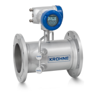
The Power Supply Circuit is connected to terminals + and – and the Data Circuit is connected
to terminals A and B. The other terminals should not be used.
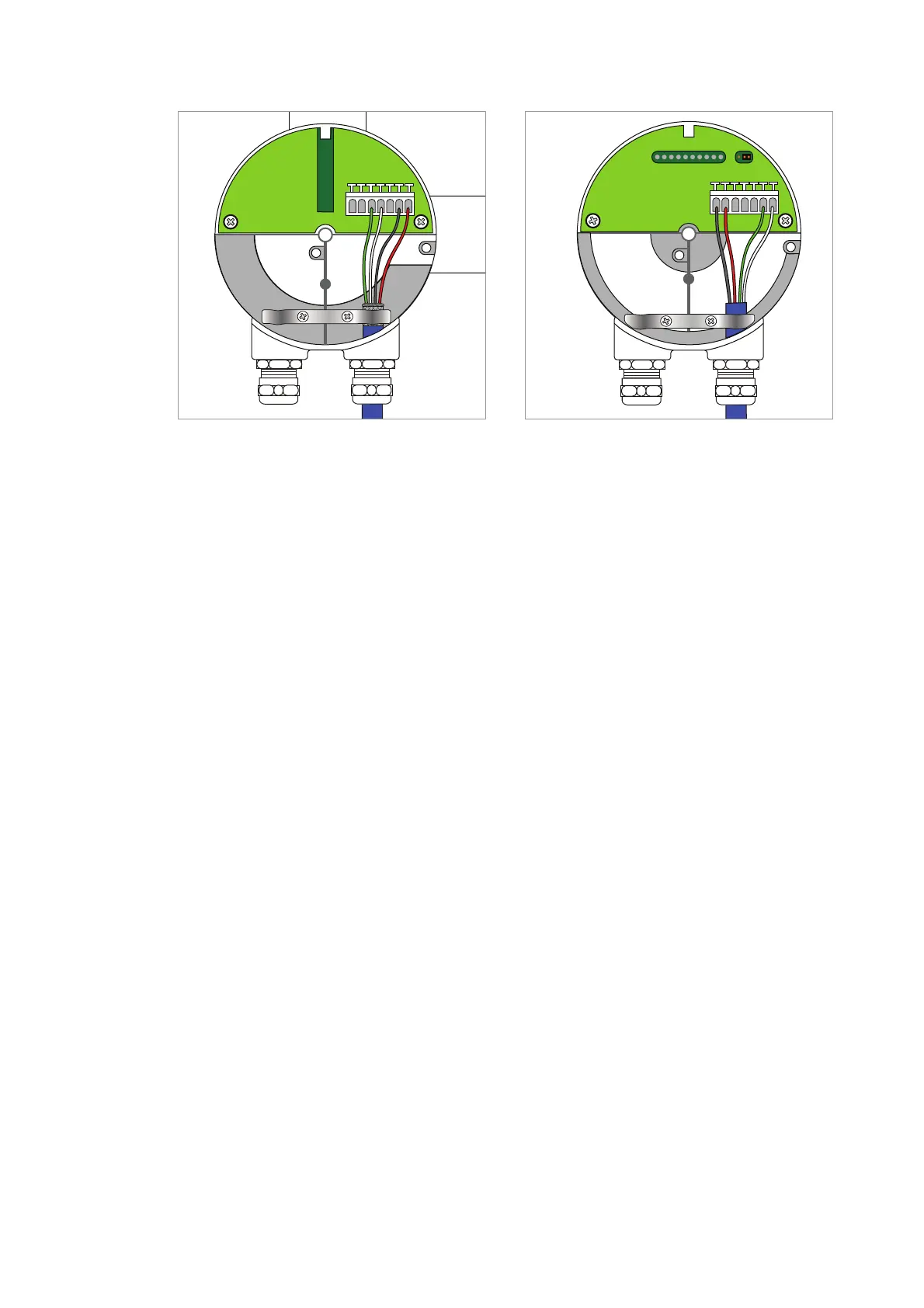
OOPPTTIIMMAASSSS // OOPPTTIIGGAASS MMaassss ffllooww sseennssoorr jjuunnccttiioonn bbooxx
The Power Supply Circuit is connected to terminals + and – and the Data Circuit is connected
to terminals A and B. The other terminals should not be used. The jumper connection deter-
mines the termination resistor for the Data Circuit.
SSccrreeeenniinngg::
Please see the illustrations above and refer to section 3.3.
3.4 Terminal Connections
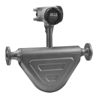
1 MFC 300F Mass flow converter junction box
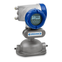
2 OPTIMASS / OPTIGAS Mass flow sensor junction box
1 2
AD OPTIMASS 300_010 Haz Areas Rev 01.qxp 05/03/2014 13:25 Page 30