7
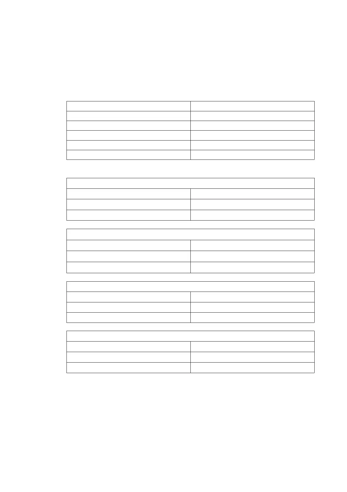
For non-Ex i signal outputs without heating jacket / insulation
Ex d connection compartment Ex e connection compartment
II 1/2 G Ex d [ib] IIC T4....T1 Ga/Gb II 1/2 G Ex de [ib] IIC T4....T1 Ga/Gb
II 2 D Ex t IIIC T185°C Db II 2 D Ex t IIIC T185°C Db
For Ex i signal outputs without heating jacket / insulation
Ex d connection compartment Ex e connection compartment
II 1/2(1) G Ex d [ia/ib] IIC T4....T1 Ga/Gb II 1/2(1) G Ex de [ia/ib] IIC T4....T1 Ga/Gb
II 2(1) D Ex t [ia Da] IIIC T185°C Db II 2(1) D Ex t [ia Da] IIIC T185°C Db
For non-Ex i signal outputs with heating jacket / insulation
Ex d connection compartment Ex e connection compartment
II 1/2 G Ex d [ib] IIC T4....T1 Ga/Gb II 1/2 G Ex de [ib] IIC T4....T1 Ga/Gb
II 2 D Ex t IIIC T195°C Db II 2 D Ex t IIIC T195°C Db
Power Supply Circuit Data Circuit
Ui = 16.5V Ui = 11.8V
Ii = 340mA Ii = 40mA
Pi = 1.3W Pi = 120mW
Ci = 35nF Ci = 35nF
Li = 10uH Li = 10uH
For Ex i signal outputs with heating jacket / insulation
Ex d connection compartment Ex e connection compartment
II 1/2(1) G Ex d [ia/ib] IIC T4....T1 Ga/Gb II 1/2(1) G Ex de [ia/ib] IIC T4....T1 Ga/Gb
II 2(1) D Ex t [ia Da] IIIC T195°C Db II 2(1) D Ex t [ia Da] IIIC T195°C Db
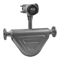
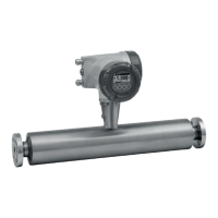
1.3 OPTIMASS 1000 / 1010C / 1300C
The OPTIMASS 1000 / 1010C mass flow sensor / mass flow meter is designed with intrinsically
safe protection type. The marking for the OPTIMASS 1000 / 1010C for versions with or without
heating jacket / insulation is as follows:
II 1/2 G Ex ib IIC T4...T1 Ga/Gb
II 2 D Ex ib IIIC T175°C Db
The input connections to the OPTIMASS 1010C for use with associated apparatus have the
following maximum values:
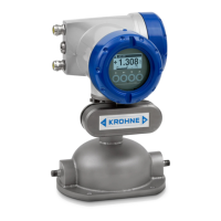
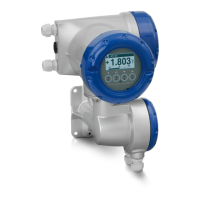
The marking for the compact OPTIMASS 1300C is as follows:
AD OPTIMASS 300_010 Haz Areas Rev 01.qxp 05/03/2014 13:24 Page 7