Do you have a question about the KSB GIW LCC Series and is the answer not in the manual?
Explains safety signs and symbols used in the manual to indicate hazards.
Emphasizes the need for qualified and trained personnel for all machine operations.
Details consequences of non-compliance and stresses adherence to all safety regulations.
Provides safety guidelines for operators and personnel performing maintenance or installation.
Provides guidelines for safe lifting and transport practices, emphasizing care due to center of gravity.
Details requirements for storing the pump unit in a dry room, protected from humidity and dirt.
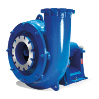
Describes the centrifugal pump's purpose, applications, and general capabilities for slurry handling.
Details pump type, model, frame size, seal types, and available options for the LCC series.
Describes three standard pump casing configurations: Hard Metal, Elastomer Lined, and Extra Heavy Hard Metal.
Details the standard 3-vane, double-shrouded impeller design and available variations.
Explains standard gland packing in a stuffing box and available options like throat bushing and mechanical seals.
Lists allowable forces and moments for pump nozzles based on ANSI/HI standards.
Details sound pressure levels and factors affecting noise in the pump and piping system.
Mentions accessories and states dimensions/weights are on installation plans.
Highlights compliance with electrical and explosion protection regulations for hazardous locations.
Specifies requirements for a strong, flat, and level foundation with proper anchor bolt placement.
Guides on leveling the base plate using shims and securing foundation bolts.
Details coupling alignment procedures using straight edges and gauges for precise setup.
Advises on insulating components and avoiding burns from hot parts.
Warns against using the pump as a pipe anchor and stresses adherence to nozzle force limits.
Explains importance of auxiliary connections and mandates use of coupling/drive guards.
Guides on re-checking alignment and ensuring the shaft rotates freely by hand.
Advises on proper electrical connection by a trained electrician, including motor protection.
Lists checks required before start-up, including operating data, oil level, and priming.
Details grease and oil lubrication for bearings, including capacities and types.
Provides instructions for adjusting gland packing and notes on seal water requirements.
Guides on venting, priming the pump and suction line, and opening valves.
Explains how to verify impeller rotation direction and potential damage from incorrect rotation.
Details cleaning procedures for plant piping, matching them to casing and seal materials.
Advises on monitoring suction strainer contamination via differential pressure.
Provides instructions for safe start-up, ensuring suction valve open and avoiding operation against closed discharge.
Guides on safe shutdown procedures, avoiding rapid deceleration and braking functions.
Details pressure, temperature, and speed limits, and switching frequency for safe operation.
Explains how medium density affects pump power input and the need to comply with specifications.
Covers storing new pumps, prolonged shutdown measures, and returning to service.
Provides general instructions on metric system usage, fastener types, and operator responsibilities.
Covers supervision of operation, noting quiet running and vibration.
Specifies intervals for oil changes based on operating hours or suspected contamination.
Outlines procedures for safe draining and disposal of pump fluids, especially hazardous ones.
Details safety precautions and steps for dismantling the pump, including securing the unit.
Provides methods for disengaging the impeller from the shaft, including specialized jigs.
Guides on lifting shells, removing elastomer liners, and disassembling expeller components.
Details draining oil, removing end covers, seals, locknuts, and the shaft/bearing assembly.
Emphasizes cleaning all parts, using new seals, and following sound engineering practices.
Details the process of heating and mounting bearings onto the shaft, including locknut procedures.
Guides on inserting the shaft with bearings into the housing, ensuring proper alignment and fit.
Details installing shaft seals (Inpro VBX) into end covers and sliding covers onto the shaft.
Provides instructions for mounting the shaft sleeve, including anti-seize application and O-ring placement.
Guides on mounting stuffing box and packing for non-expeller and expeller configurations.
Guides on mounting the cartridge bearing assembly to the pedestal, ensuring proper alignment.
Details mounting the expeller casing, expeller plate, and expeller itself, including preliminary adjustment.
Guides on seating the pump shell onto the pedestal, ensuring gasket fit.
Provides instructions for seating elastomer liners into metal casings, emphasizing non-petroleum lubricants.
Details mounting the impeller onto the shaft, using anti-seize and gaskets, and checking clearances.
Guides on bolting the suction liner to the suction plate and ensuring proper protrusion.
Explains how to adjust bearing housing for minimum impeller-to-liner clearance and proper seating.
Details procedures for optimizing expeller performance and setting clearances, including warnings.
Provides torque values for bearing locknuts and clamp bolts for various shaft sizes.
Explains the function of water purge for gland packing, including pressure, temperature, and water quality requirements.
Discusses sump capacity, solids flow, vortex prevention, and frothing considerations.
Explains cavitation, NPSH requirements, and how to maximize available NPSH.
Advises on pipeline design, including slope, diameter, and avoiding surge conditions for slurries.
Discusses pump operation at the intersection of pump and system curves, and conditions affecting performance.
Lists checks for low flow rate, including pump correctness, wear, motor, speed, and NPSH.
Explains causes of high bearing temperature, such as fluid, misalignment, or worn parts.
Lists potential causes of bearing contamination, including leakage and improper maintenance.
Refers to packing section and lists causes of stuffing box issues like high temperature or leakage.
Identifies causes of pump casing overheating, including hot fluid and blocked discharge.
Lists common causes of pump leakage, such as defective gaskets or worn casings.
Covers checks for motor overload, including motor specifications, fluid properties, and alignment.
Lists potential causes of vibration and noise, such as cavitation, rubbing, or imbalance.
Provides torque values for various metric fastener sizes and thread types.
Provides reference to assembly drawings and bills of material for the pump.
Mentions supplements providing additional information for optional equipment.
Lists pump components with part numbers and designations for LCC-M and LCC-H models.
Provides detailed dimensions for pump and shaft sizes in inches and mm.
Lists connection flange types and dimensions for different pump sizes.
Lists materials used in the pump assembly, cross-referenced to drawings.
Shows the general arrangement of motor position 1 for the pump unit.
Lists design operating conditions such as flow, head, slurry properties, and power.
Recommends stocking wearing parts and notes requirements for abrasive/corrosive applications.
Instructs how to place an order, including required information and contact details.
| Manufacturer | KSB |
|---|---|
| Solids Handling | High |
| Series | GIW LCC |
| Application | Mining, dredging, and industrial slurry handling |
| Operating Pressure | Varies by model |
| Materials | High Chrome Iron, Various Alloys |
| Impeller Type | Closed, Semi-Open |
| Seal Options | Mechanical seals or gland packing |
| Drive Options | Electric motor |