LCC
10
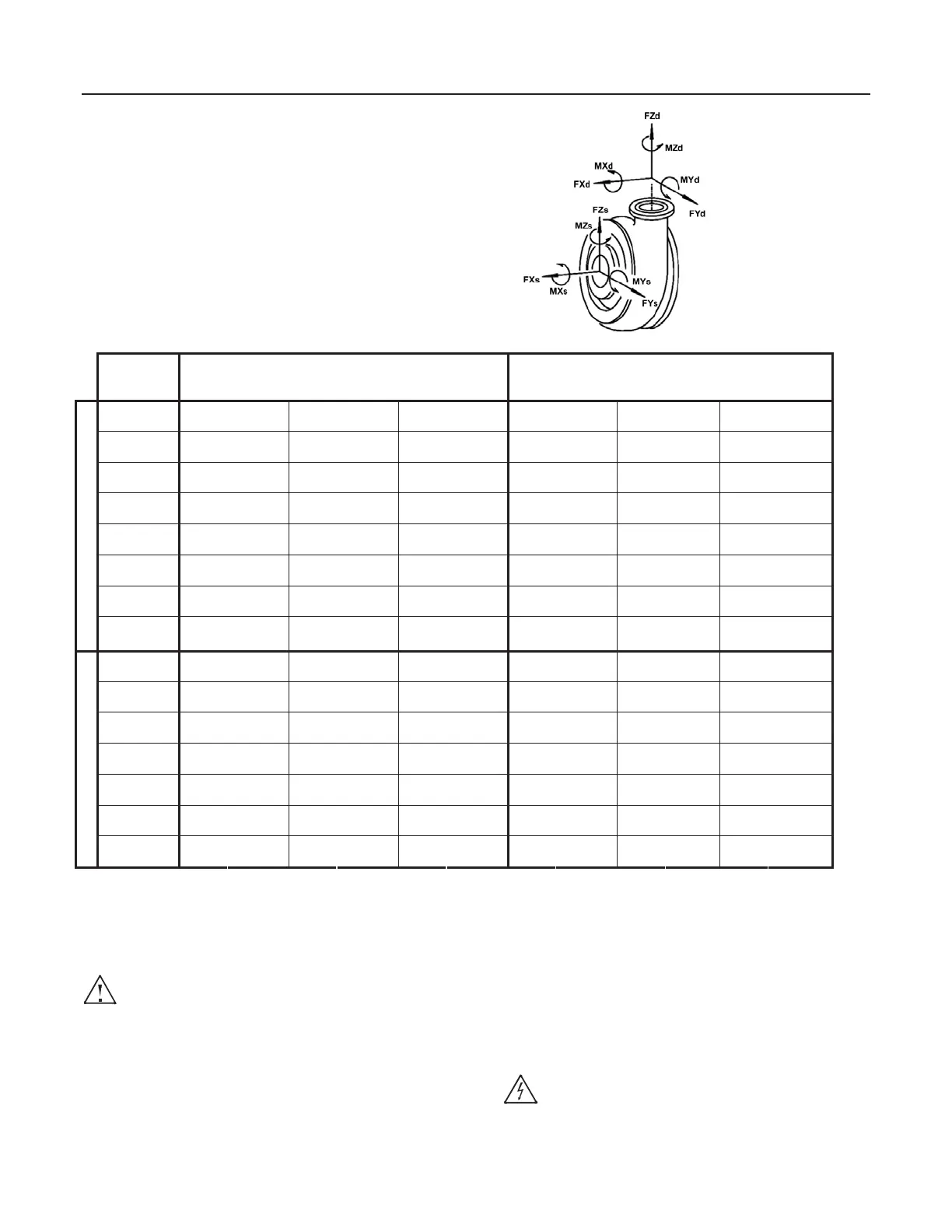
4.3.5 Permissible Forces and Moments at the Pump
Nozzles
Allowable combined branch loads applicable for all GIW
slurry pumps. Methods based on ANSI/HI 12.1-12.6-2005
Slurry Pump Standard. Coordinate system per HI/ANSI
9.6.2 and API 610 (see figure). Loads generally exceed
HI/ANSI 9.6.2-2008 table 9.6.2.1.4a and API 610-2004,
Table 4. Higher allowable loads may be possible
depending on individual pump configuration and operating
conditions. Contact your GIW Application Engineer for
more information.
4.3.6 Noise Characteristics
If running within the normal limits of operation and on clear
liquid, the sound pressure level for the pump alone does
not exceed 80 dB at one meter.
The addition of coarse solids, froth or cavitating
conditions can significantly increase the noise
levels in both the pump and piping. If accurate noise
levels are required for these conditions, field-testing will be
required.
Sound pressure levels from motor and gear reducer must
be added to the above in accordance with standard
acoustic formulas, taking into account the distance
between units. For belt driven units, add an additional 2
dB.
4.4 Accessories
Couplings, pulleys, belts, motor mounts and/or base plates
may be provided. Refer to the bill-of-materials, data
sheets and/or drawings for further information.
4.5 Dimensions and Weights
Dimensions and weights are listed on the pump
installation plan
.
5 Installation at Site
5.1 Safety Regulations
Electrical equipment operated in hazardous
locations must comply with the applicable
explosion protection regulations. This is indicated on the
motor rating plate. If the equipment is installed in
hazardous locations, the applicable local explosion
protection regulations and the regulations of the test
Allowable Forces lbs (N) Allowable Moments ft-lbs (N-m)
Flange
Size
F
X
F
Y
F
Z
M
X
M
Y
M
Z
2 inch
(50 mm)
2490 (11070) 1980 (8800) 3000 (13340) 2640 (3570) 2640 (3570) 4000 (5420)
3 inch
(75 mm)
2730 (12170) 2170 (9680) 3290 (14670) 2900 (3930) 2900 (3930) 4390 (5960)
4 inch
(100 mm)
2980 (13270) 2370 (10550) 3590 (15990) 3160 (4290) 3160 (4290) 4790 (6500)
6 inch
(150 mm)
3470 (15440) 2760 (12280) 4180 (18610) 3680 (4990) 3680 (4990) 5580 (7570)
8 inch
(200 mm)
3950 (17580) 3140 (13980) 4760 (21190) 4200 (5690) 4200 (5690) 6360 (8620)
10 inch
(250 mm)
4420 (19690) 3520 (15660) 5330 (23730) 4700 (6380) 4700 (6380) 7130 (9670)
12 inch
(300 mm)
4890 (21780) 3890 (17320) 5900 (26240) 5210 (7070) 5210 (7070) 7900 (10710)
D
i
s
c
h
a
r
g
e
P
i
p
e
14 inch
(350 mm)
5350 (23830) 4260 (18950) 6450 (28710) 5710 (7740) 5710 (7740) 8650 (11730)
3 inch
(75 mm)
3290 (14670) 2730 (12170) 2170 (9680) 4390 (5960) 2900 (3930) 2900 (3930)
4 inch
(100 mm)
3590 (15990) 2980 (13270) 2370 (10550) 4790 (6500) 3160 (4290) 3160 (4290)
6 inch
(150 mm)
4180 (18610) 3470 (15440) 2760 (12280) 5580 (7570) 3680 (4990) 3680 (4990)
8 inch
(200 mm)
4760 (21190) 3950 (17580) 3140 (13980) 6360 (8620) 4200 (5690) 4200 (5690)
10 inch
(250 mm)
5330 (23730) 4420 (19690) 3520 (15660) 7130 (9670) 4700 (6380) 4700 (6380)
12 inch
(300 mm)
5900 (26240) 4890 (21780) 3890 (17320) 7900 (10710) 5210 (7070) 5210 (7070)
S
u
c
t
i
o
n
P
i
p
e
14 inch
(350 mm)
6450 (28710) 5350 (23830) 4260 (18950) 8650 (11730) 5710 (7740) 5710 (7740)
 Loading...


