LCC
8
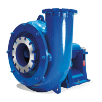
Fig 4.3-4 Gland Packing (non-expeller)
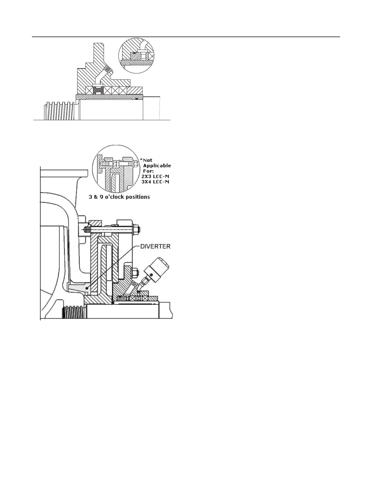
Fig 4.3-5 Typical Expeller Arrangement
Expeller seals are used in pump applications where limited
or no gland flush water is readily available or where it is not
compatible with the process fluid. A second rotating impeller
contained in a separate casing creates a lower pressure at
the stuffing box seal area. This allows the shaft sleeve to be
grease lubricated and run with only enough packing
compression to seal the pump.
Unlike mechanical seals, expellers must be carefully
selected for each application and specific operating
conditions. Expellers require additional driver horsepower,
which must be accounted for during motor selection.
Changes to head, flow, pump speed, process solids or sump
level after the pump has been installed can affect the
functionality of an expeller sealing system.
Correct installation, adjustment and operating procedures
are extremely critical to the proper function and life of these
seals. Extensive testing has shown that the following
guidelines can help keep the expeller system operating
properly while prolonging the life of wear components.
Further engineering review is recommended for expeller
operation outside these guidelines.
Particle size – The D50 should be kept between 200 and
1500 microns.
Slurry SG – The Specific Gravity of the slurry should remain
below 1.35.
Solids – Slurries that could deposit scale on pump surfaces
should be avoided.
Flow rate – Stay between 0.5 and 1.3 times the Best
Efficiency Point (Q
BEP
).
Flushing – Solids in the process flow can precipitate out
when the pump stops and build up in the expeller chamber.
Over time, this reduces efficiency and accelerates wear. The
system should always be purged with clear water for at least
15 minutes prior to stopping the pump. Starting the system
on clear water will help the expeller displace solids. For
applications where precipitate buildup in the expeller
chamber is unavoidable, intermittent gland water flush may
be necessary.
When the stuffing box does not have flush water, the
packing must be lubricated with grease or oil. Graphite
packing such as Tuf-Pak 400 is recommended. Manual or
automatic grease dispensers are available depending on the
application. Twisting the cap in on the manual units will add
a small amount of grease to the packing. These are refilled
by removing the cap and packing the cup with lubricant.
Automatic greasers use a spring driven piston to maintain a
steady supply of grease. These are refilled by connecting a
grease gun to the fitting on the side of the unit. Note that
extremes in temperature can alter the amount of lubricant
supplied to the packing and must be accounted for. Springs
are available for the automatic greaser with three different
tension levels to control the flow of grease.
New expeller pumps are equipped with a diverter ring
pressed into the hub area of the pump casing. This acts as a
baffle to help reduce the amount of solids entering the seal
chamber. The diverter can be ordered as a service part and
retrofit into earlier units. For diverter installation see
supplement 11.4.
It is important to operate the expeller pump within the speed
limitations and operating conditions specified in the original
design parameters. Wide variations in flow rate and solids
can allow particles to accumulate in the expeller chamber,
which may result in a plugging or premature component
failure. Any change in the operating conditions should be
discussed with your GIW / KSB representative to establish if
the new conditions are suitable for the equipment
.
Throat Bushing O ptio
 Loading...


